Method and apparatus for aligning data in a wide, high-speed, source synchronous parallel link

a synchronous parallel link and data technology, applied in the direction of instruments, baseband system details, generating/distributing signals, etc., can solve the problems of limiting the speed of the bus, the skew between the pins of the clock increases, and the difficulty of driving the clock becomes difficul

Inactive Publication Date: 2005-03-24
CISCO TECH INC
View PDF10 Cites 30 Cited by
  • Summary
  • Abstract
  • Description
  • Claims
  • Application Information

AI Technical Summary

Benefits of technology

[0006] One embodiment of the invention allows the clock period of the transmit and receive core clocks to get smaller than the skew between the copies of source-synchronous clock. The maximum frequency of operation of the link is thereby increased to the limit reachable for sampling a small number of data pins with a source-synchronous clock received on a pair (clock high and clock low) of clock pins. There is no limit imposed because of skew between multiple copies of source-synchronous clocks.

Problems solved by technology

At higher speed, being able to drive a clock becomes challenging especially when the data pins are driven and sampled on both edges of the clock.
One of the limitations on speed derives from the fact that as the number of data pins gets large, the skew between those pins increases, where Clock Skew is the variation in the transition point of a clock signal due to delay in the propagation path.
Since all pins need to be sampled with the same clock, clock skew limits the speed of the bus.

Method used


Image

  • Method and apparatus for aligning data in a wide, high-speed, source synchronous parallel link
  • Method and apparatus for aligning data in a wide, high-speed, source synchronous parallel link
  • Method and apparatus for aligning data in a wide, high-speed, source synchronous parallel link

Examples


Embodiment Construction

[0021] Reference will now be made in detail to various embodiments of the invention. Examples of these embodiments are illustrated in the accompanying drawings. While the invention will be described in conjunction with these embodiments, it will be understood that it is not intended to limit the invention to any embodiment. On the contrary, it is intended to cover alternatives, modifications, and equivalents as may be included within the spirit and scope of the invention as defined by the appended claims. In the following description, numerous specific details are set forth in order to provide a thorough understanding of the various embodiments. However, the present invention may be practiced without some or all of these specific details. In other instances, well known process operations have not been described in detail in order not to unnecessarily obscure the present invention.

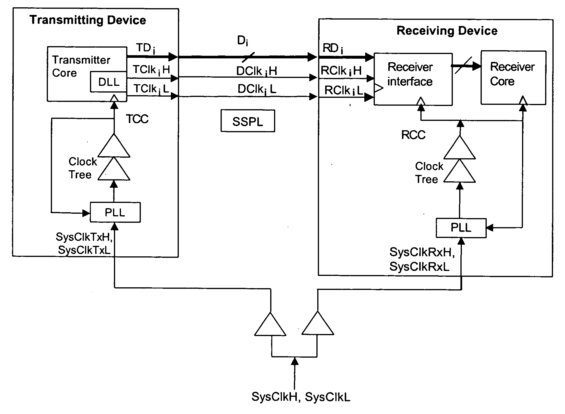
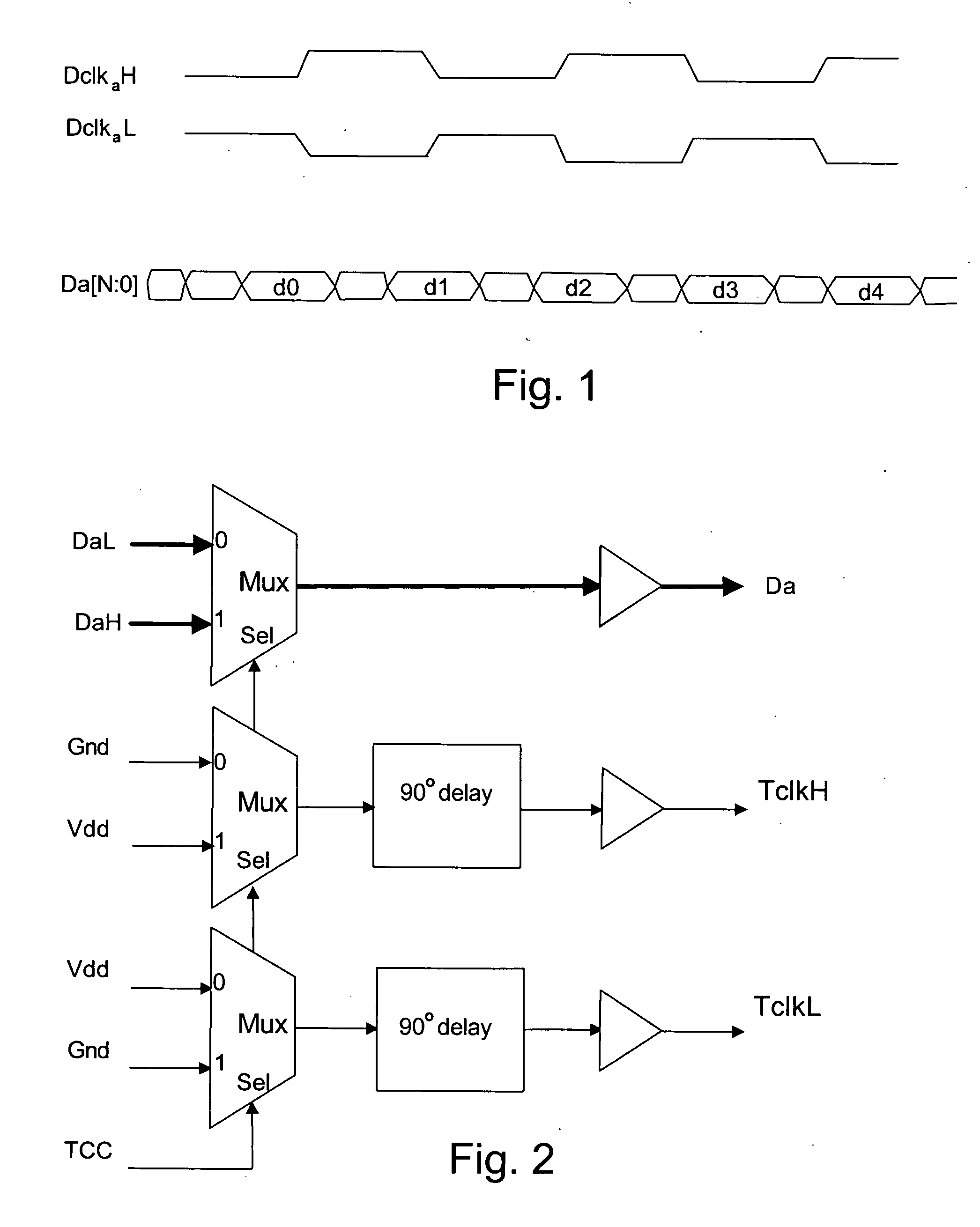
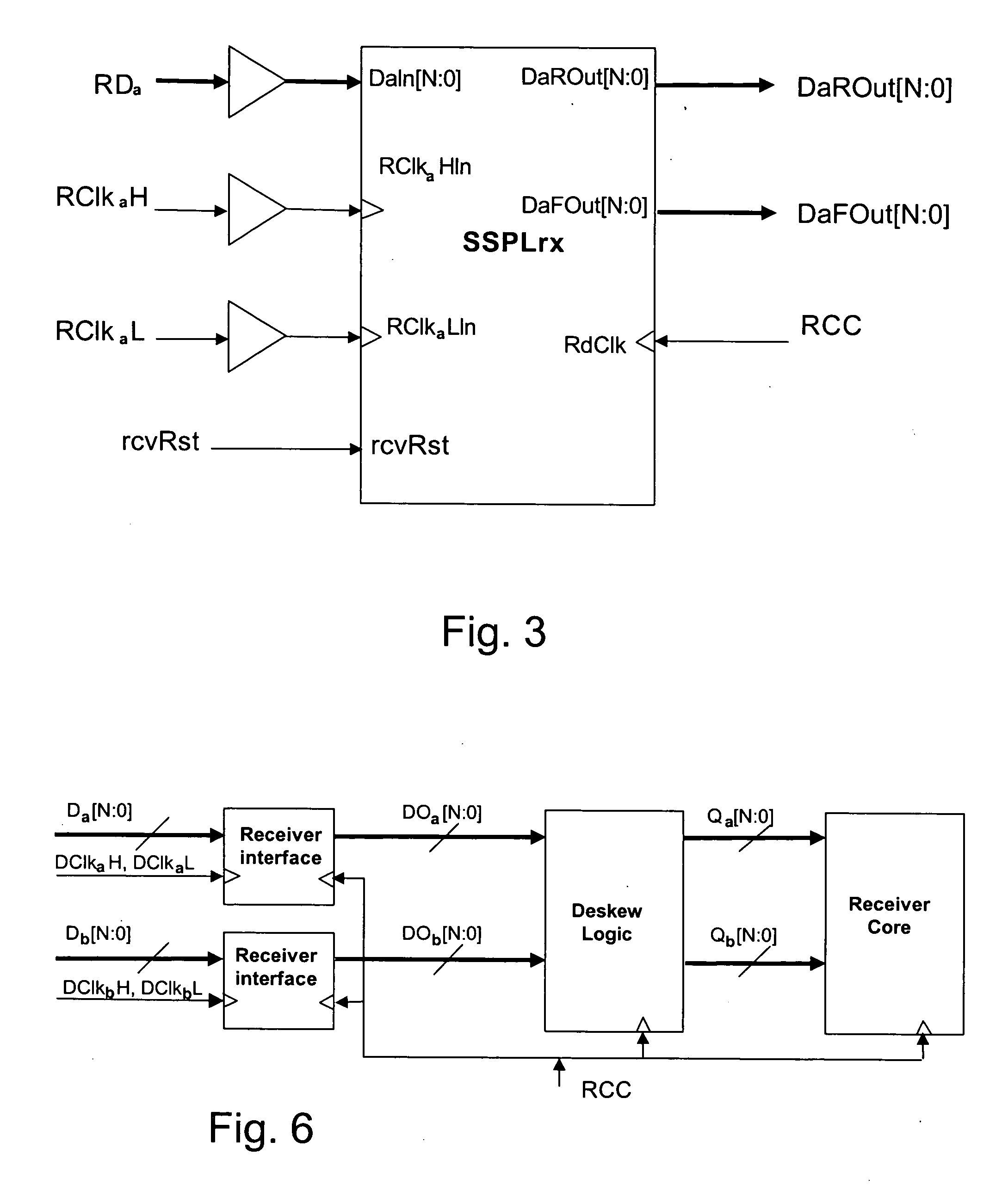
[0022] Several embodiments will now be described to implement a high-speed source-synchronous parallel ...


PUM


Abstract

A source-synchronous parallel interface divides a wide data bus into clock-groups including a sub-group of the data lines and a clock line carrying a copy of the transmit clock. The traces in a clock-group are located physically close together to minimize skew between the signals carried on the traces of the clock-group. Deskew logic on the receiver compensates for skew between received clock-group signals.

Description

RELATED APPLICATIONS [0001] This application is a continuation in part of the commonly-assigned United States patent application entitled HIGH-SPEED MEMORY FOR USE IN NETWORKING SYSTEMS, filed Jun. 16, 2003, Ser. No. 10 / 462,866, which is hereby incorporated by reference for all purposes.BACKGROUND OF THE INVENTION [0002] The source-synchronous bus has been used to increase the speed of buses in many designs. Data and clock are sourced from the same device on the bus. The receiving device uses the clock from the bus to sample the data on the bus. Since the clock and data are driven and distributed similarly, they have similar delays and hence such buses can be run faster than buses using other clocking schemes. [0003] At higher speed, being able to drive a clock becomes challenging especially when the data pins are driven and sampled on both edges of the clock. This is referred to as double-data rate or DDR. [0004] One of the limitations on speed derives from the fact that as the num...

Claims


Application Information

Patent Timeline
Patent Type & Authority Applications(United States)
IPC IPC(8): G06F12/00G06F13/42
CPCG06F13/4291H04J3/0632H04L25/14H04L7/041H04L7/0008
Inventor BHATTACHARYA, DIPANKARPRIYADARSHAN, BANGALORELEE, JAUSHINLE-BOULCH, FRANCOIS GAUTIER
Owner CISCO TECH INC
Why Eureka
Try Eureka