
Mechanism to enhance observability of integrated circuit failures during burn-in tests

a technology of integrated circuit and burn-in test, which is applied in the direction of electronic circuit testing, measurement devices, instruments, etc., can solve the problems of difficult monitoring of multiple devices on a board, limited number of devices can be burned-in, and weak devices may show failures, etc., to increase diagnostics and enhance fault isolation. scope

Active Publication Date: 2005-03-24
TEXAS INSTR INC
View PDF5 Cites 7 Cited by
  • Summary
  • Abstract
  • Description
  • Claims
  • Application Information

AI Technical Summary

Benefits of technology

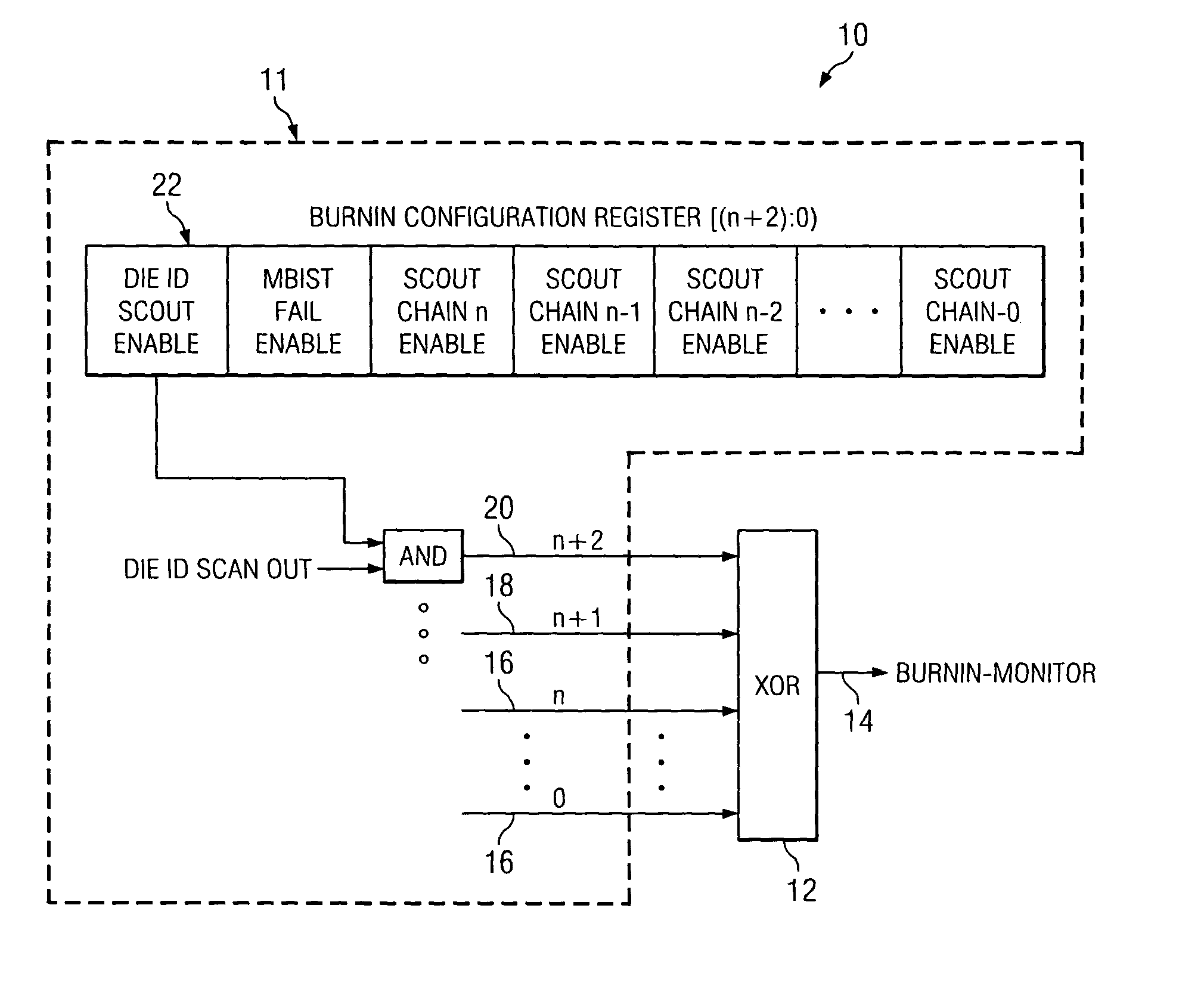
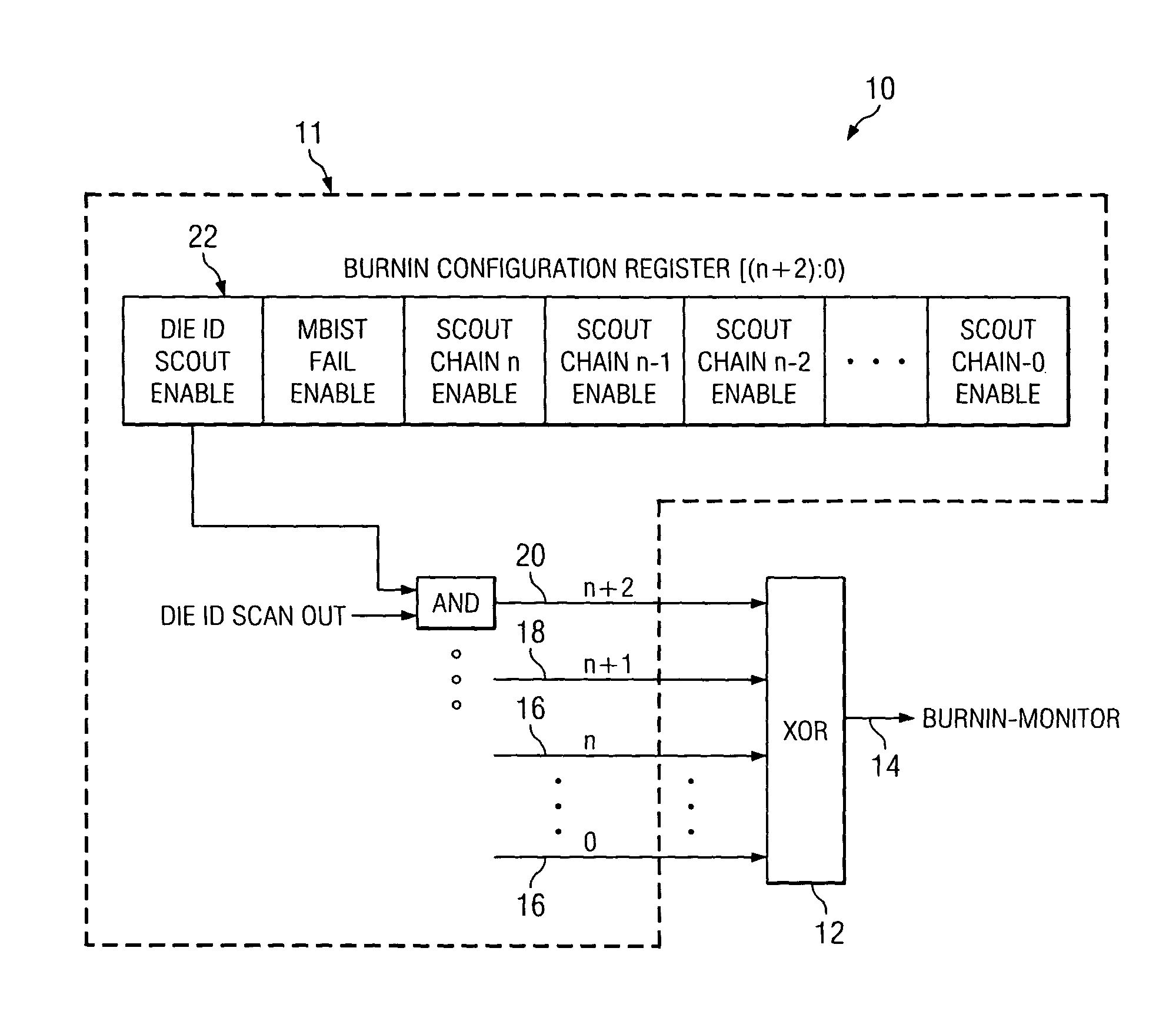
[0006] The present invention is directed to a technique for enhancing observability of IC failures during burn-in tests. Scan ATPG (Automatic Test Pattern Generation) and memory BIST (Built In Self Test) patterns are monitored during the burn-in tests to provide a mechanism for observing selective scan chain outputs and memory BIST status outputs.
[0007] A burn-in stimulus is applied to the device under test through scan channels. The outputs of all the scan chains are combined into a monitor output using an Ex-OR logic cone which is brought out at the device level. A mechanism is provided to select a particular set of one or more scan chains to be driven into the Ex-OR cone. Further, the memory BIST status signals (combined output derived from the Fail / Go-NoGo or other such status signals of all active controllers) and the DieID scan chain output are also selectively enabled to drive the monitor output through the Ex-OR cone. This process is advantageous in that it 1) provides the desired visibility and 2) enhances the scope for fault isolation during burn-in process.
[0008] In one aspect of the invention, a technique is provided that allows for increased diagnostibility in the presence of Ex-OR logic beyond that presently available using known Ex-OR approaches to generate monitored outputs.

Problems solved by technology

Due to these extreme stress conditions, weak devices may show failures.
Depending upon the complexity of the device, the burn-in board configuration and the burn-in oven, only a limited number of devices can be burned-in at the same time.
With limited pin monitoring capability of the oven, monitoring several pins of multiple devices on a board becomes very challenging.
Such limitations regarding observability prevent any substantial scope of fault isolation.

Method used


Image

  • Mechanism to enhance observability of integrated circuit failures during burn-in tests
  • Mechanism to enhance observability of integrated circuit failures during burn-in tests

Examples


Embodiment Construction

[0028] The Ex-OR approach to generate a monitored output during integrated circuit burn-in testing is known, as stated herein before. The present inventors recognized that this known approach however, is disadvantageous in that it increasingly limits the scope of fault isolation as the desired number of devices under test increases, and therefore the available number of monitor outputs decreases.

[0029] Looking now at the FIGURE, a block diagram illustrates a system 10 for enhancing observability of integrated circuit failures during burn-in testing according to one embodiment of the present invention. The system 10 consists of n+2 AND gates (only one AND gate is depicted in the FIGURE), a configuration register 22 of n+2 width, and a single XOR gate 12. The present inventors alone realized a selection mechanism (sub-system) 11 for individual scan chain 16 and memory built-in self-test (BIST) status 18 outputs to implement this system 10.

[0030] The implementation shown in the FIGUR...


PUM


Abstract

A system and method enhance observability of IC failures during burn-in tests. Scan automatic test pattern generation and memory built-in self-test patterns are monitored during the burn-in tests to provide a mechanism for observing selective scan chain outputs and memory BIST status outputs.

Description

BACKGROUND OF THE INVENTION [0001] 1. Field of the Invention [0002] This invention relates generally to semiconductor integrated circuit (IC) burn-in testing, and more particularly to a technique for enhancing observability of IC failures during burn-in tests. [0003] 2. Description of the Prior Art [0004] Burn-in testing for a semiconductor integrated circuit (IC) device is carried out to eliminate weak devices that are most likely to fail during early life of the product. The test is performed within a burn-in oven by placing multiple devices on a burn-in board at typically a 125 degrees Centigrade (C) temperature and by applying a higher voltage than the normal operating voltage to the device. Due to these extreme stress conditions, weak devices may show failures. To detect these failures during the test itself, the device functionality can be monitored. Depending upon the complexity of the device, the burn-in board configuration and the burn-in oven, only a limited number of devi...

Claims


Application Information

Patent Timeline
Patent Type & Authority Applications(United States)
IPC IPC(8): G01R31/28G01R31/3185G01R31/319G11C29/44
CPCG01R31/2856G01R31/318577G11C2029/3602G11C29/44G11C2029/3202G01R31/31905
Inventor BAREVADIA, GORDHANAGASHE, ANUPAMA ANIRUDDHAKRISHNAMOORTHY, NIKILAPAREKHJI, RUBIN AJITSIMPSON, NEIL J.
Owner TEXAS INSTR INC
Learn More