Wave gear device

a gear device and wave technology, applied in the direction of gearing, gearing elements, hoisting equipment, etc., can solve the problems of deteriorating the service life and strength of the pinion cutter, and the fatigue strength of the flexible external gear is greatly degraded, so as to increase the thickness of the tooth bottom side portion, prevent the degradation of the service life and strength of the pinion cutter, and increase the ratcheting torque

Inactive Publication Date: 2005-03-31
HARMONIC DRIVE SYST IND CO LTD
View PDF4 Cites 33 Cited by
  • Summary
  • Abstract
  • Description
  • Claims
  • Application Information

AI Technical Summary

Benefits of technology

[0016] In the rigid internal gear and/or the flexible external gear of the wave gear device of the present invention, the tooth profiles thereof are defined based on the basic rack tooth profile, and each tooth profile shape of the dedendum portion thereof is modified so that the pressure angle on the dedendum portion is less than the standard pressure angle. Setting the tooth profile shape in this manner allows an increase in the thickness of the tooth bottom side portion to be kept small when the tooth depth thereof is increased in order to increase the ratcheting torque, and the tooth thickness thereof is increased in order to prevent degradation of the

Problems solved by technology

This causes to deteriorate the service life and strength of the pinion cutter.
However, when the tooth thickness is increased, be

Method used


Image

  • Wave gear device
  • Wave gear device
  • Wave gear device

Examples


Embodiment Construction

[0021] An embodiment of a wave gear device according to the present invention will be described with reference to the drawings.

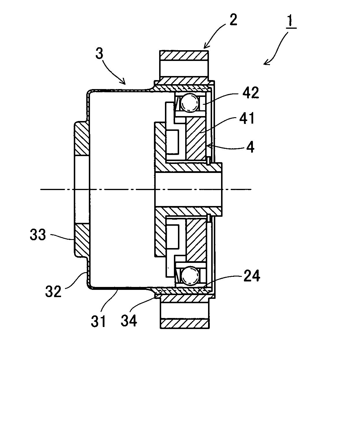
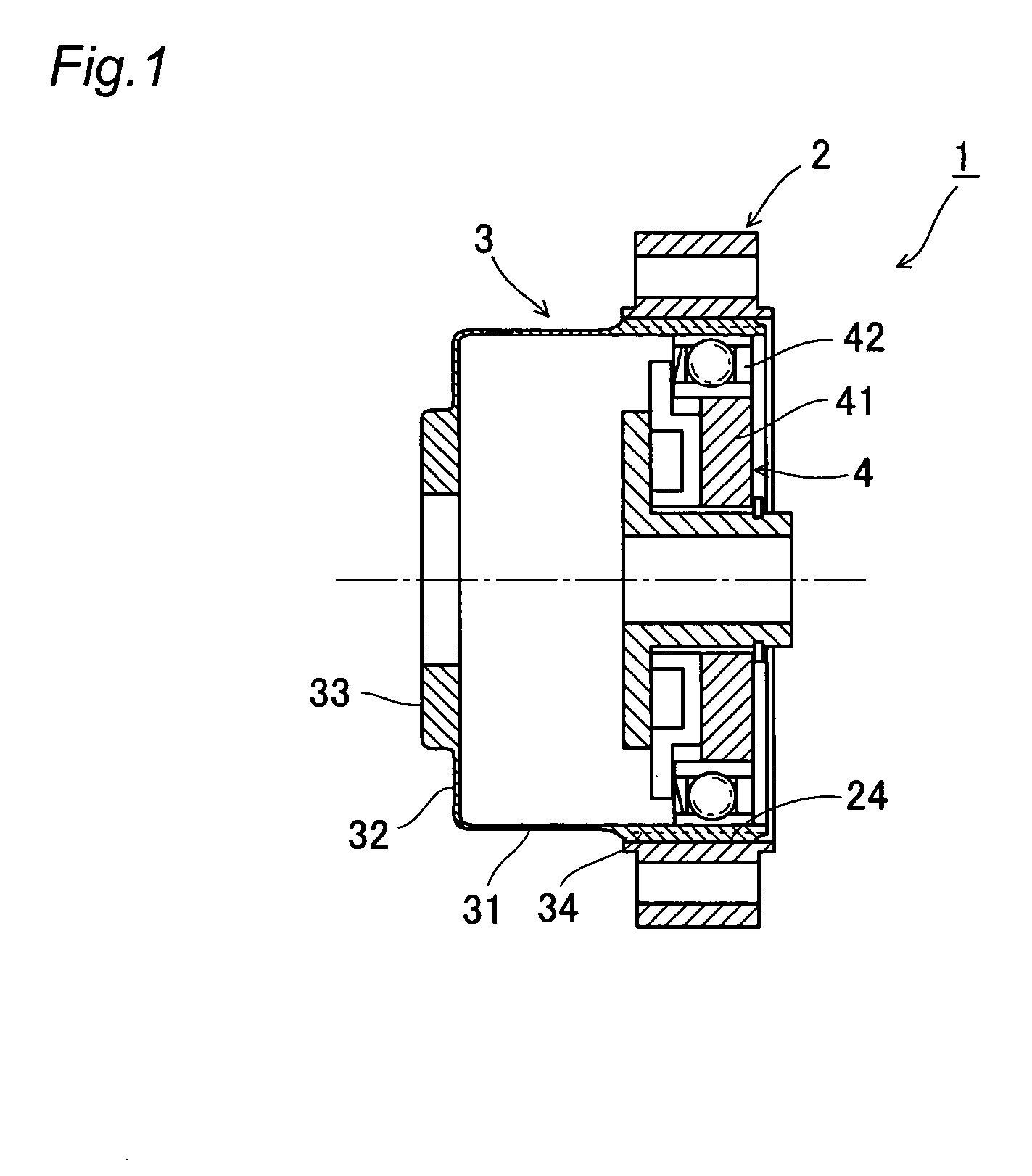
[0022]FIG. 1 is a cross-sectional view of a wave gear device, and FIG. 2 is a schematic diagram showing gears of the wave gear device in an engaged state. A wave gear device 1 comprises a circular rigid internal gear 2, a flexible external gear 3 coaxially disposed therein, and a wave generator 4 fitted therein. The flexible external gear 3 is of a cup shape having a cylindrical body portion 31, an annular diaphragm 32 extending radially and inwardly from one end of the body portion 31, and a discoid boss 33 formed in a continuous fashion on an internal peripheral edge of the annular diaphragm 32. External teeth 34 are formed on an external peripheral surface portion of an open end side of the body portion 31.

[0023] The wave generator 4 comprises an elliptically contoured rigid cam 41, and a wave bearing 42 having flexible inner and outer races. The inner ...


PUM


Abstract

A wave gear device has a rigid internal gear, a flexible external gear, and a wave generator. The tooth profiles of both gears are initially defined by a basic rack tooth profile shape. The lower parts of the dedendum portions of these tooth profiles are modified by curves C2 and C3 having pressure angles α2 and α3 that are less than the standard pressure angle α1 of the basic rack tooth profile shape C1. An increase in thickness of the tooth bottom side can be minimized even if the tooth depth is increased and the tooth thickness/tooth space ratio changed to increase the tooth thickness. Hence, the ratcheting torque of a wave gear device having a high reduction gear ratio can be increased without reducing the service life and strength of a pinion cutter for the rigid internal gear, or the fatigue strength of the flexible external gear.

Description

BACKGROUND OF THE INVENTION [0001] 1. Field of the Invention [0002] The present invention relates to a wave gear device with a high reduction gear ratio, and more particularly to a wave gear device with a high tooth-depth tooth profile that is advantageous for increasing ratcheting torque. [0003] 2. Description of the Related Art [0004] Since it was proposed in JP-B 45-41171 that an involute tooth profile could be used for a wave gear device, an easy-to-cut basic rack tooth profile (involute tooth profile) has been widely adopted as the basic tooth profile of the gears constituting the wave gear device. Examples of the basic rack tooth profile adopted for an circular rigid internal gear and a flexible external gear of a wave gear device are indicated as a “conventional C / S tooth profile” and a “conventional F / S tooth profile” in FIG. 3, and these are shown with broken lines. It is apparent from this diagram that in the basic rack tooth profile the pressure angle increases from the p...

Claims


Application Information

Patent Timeline
IPC IPC(8): F16H49/00F16H1/32F16H55/08
CPCF16H49/001Y10T74/19F16H55/0833
Inventor KIYOSAWA, YOSHIHIDE
Owner HARMONIC DRIVE SYST IND CO LTD
Why Eureka
Try Eureka