Eureka AIR delivers breakthrough ideas for toughest innovation challenges, trusted by R&D personnel around the world.

Modular weight bar

Inactive Publication Date: 2005-03-31
BAKER HUGHES INC
View PDF10 Cites 3 Cited by
  • Summary
  • Abstract
  • Description
  • Claims
  • Application Information

AI Technical Summary

Benefits of technology

[0019] A tapered edge can be provided on the sliding sleeve and formed for insertion between the at least one slip and the body as the sliding sleeve is upwardly urged, this action outwardly extends the at least one slip into engaging contact with the wellbore. Further, the engagement system of the modular weight bar engages the modular weight bar within the wellbore and suspends the it within the wellbore, thereby enabling the wireline tool to be deployed to a depth greater than the selected depth within the wellbore. The modular weight bar can further comprise a coaxial annular opening allowing for passage of a wireline therethrough.
[0024] Accordingly, one of the advantages provided by the present invention is the ability to operate a downhole tool within a pressurized wellbore, where the downhole tools can be lowered into the pressurized wellbore by adding weight to the downhole tool. Further, an additional advantage provided by the present invention is the ability to selectively separate and deploy the added weight from the downhole tool within the wellbore, and lower the downhole tool into the wellbore at deeper depths than if the weight were still combined with the downhole tool.

Problems solved by technology

However, when conveying objects by wireline, a force applied from above the wireline cannot urge the objects downhole since wireline is generally flexible and has no compressive strength to push the objects downward into the wellbore to overcome the pressure differential.
However, use of the weight bar in conjunction with a downhole tool to overcome wellbore pressure differentials presents many problems and has many limitations.
Some of the problems with weight bars are that addition of a weight bar to a downhole tool reduces the depth at which a downhole tool can be lowered into a wellbore, weight bars cannot be used on all oilrigs due to height restrictions, and the presence of weight bars proximate to logging tools can diminish the accuracy of logging data.
In situations where the downhole tool is being lowered deep into a wellbore, such as in excess of a few thousand feet, the mass of wireline within the wellbore adds to the overall weight of what is being supported by the wireline.
While the total weight of the wireline in the wellbore has little effect on the segment of wireline proximate to the downhole tool, the segment of wireline proximate to the surface is greatly affected, since the tool and all associated wireline is supported by the wireline proximate to the surface.
While the strength of the wireline can be increased by using thicker wireline this does not help the weight issue since thicker wireline also has an increased mass per unit length.
Further, thicker wireline also results in a need for more added weight since increasing the cross sectional area of the wireline increases the pressure differential across the wireline.
Space limitations are also a problem with some currently developed weight bars.
In some instances the oilrig platform at the wellbore surface has limited vertical space and cannot accommodate such a long length.
Addition of a weight bar also causes problems when using downhole tools in deviated wellbores.
When this is the case, the added loading caused by dragging the downhole tool along the borehole can take the wireline to its yield point and stretch the wireline that results in a jerky motion of the wireline tool up the wellbore instead of a smooth controlled ascent.
This is especially a problem when the downhole tool is a well logging device because the jerking motion results in poor logging results since the well logging requires a steady constant ascent to obtain proper readings.
Even though many are equipped with centralizers, the added mass of a weight bar can temporarily deform the centralizers and eccentrically position the downhole tool within the wellbore.
Downhole tools such as logging devices, perforating guns, or collar locators, may not perform their intended function if they are not centrally situated within the wellbore.
Certain dangers exist with many downhole tools that pose hazards to the downhole tool, the personnel handling the tool, or both.
For example, production logging tools are susceptible to structural damage, especially when deployed in difficult or deviated wells.
Even when extra care is taken to protect these tools, these tools can be damaged if they strike the inner surface of the wellbore or the production string.
Some downhole tools contain radioactive sources that are potentially harmful to the workers employing the tool, thus radioactive monitoring is necessary in order to use these types of tools.
Other downhole tools vulnerable to damage during use are perforating guns.
Perforating guns can also be mechanically damaged during insertion into the wellbore, especially when they are in close contact with valves at the wellbore surface such as well control valves, master valves, swab valves, and sub-sea safety valves.
Another downhole tool that poses a risk is a chemical cutter.
Chemical cutters, while typically sealed, can still leak flammable chemicals that will combust when exposed to an ignition source.
Ignition of the chemicals from a chemical cutter at this time can likely result in serious personal injury or death.
Another hazard to wellbore personnel is from some wells that contain hazardous chemicals within the wellbore that will contact and coat the downhole tool.
Consequently when the downhole tool is removed from the wellbore the personnel stationed at the wellbore surface are at risk of being contaminated or injured by the hazardous substance.

Method used


Image

  • Modular weight bar
  • Modular weight bar
  • Modular weight bar

Examples


Embodiment Construction

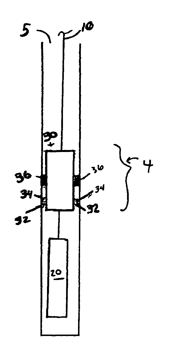
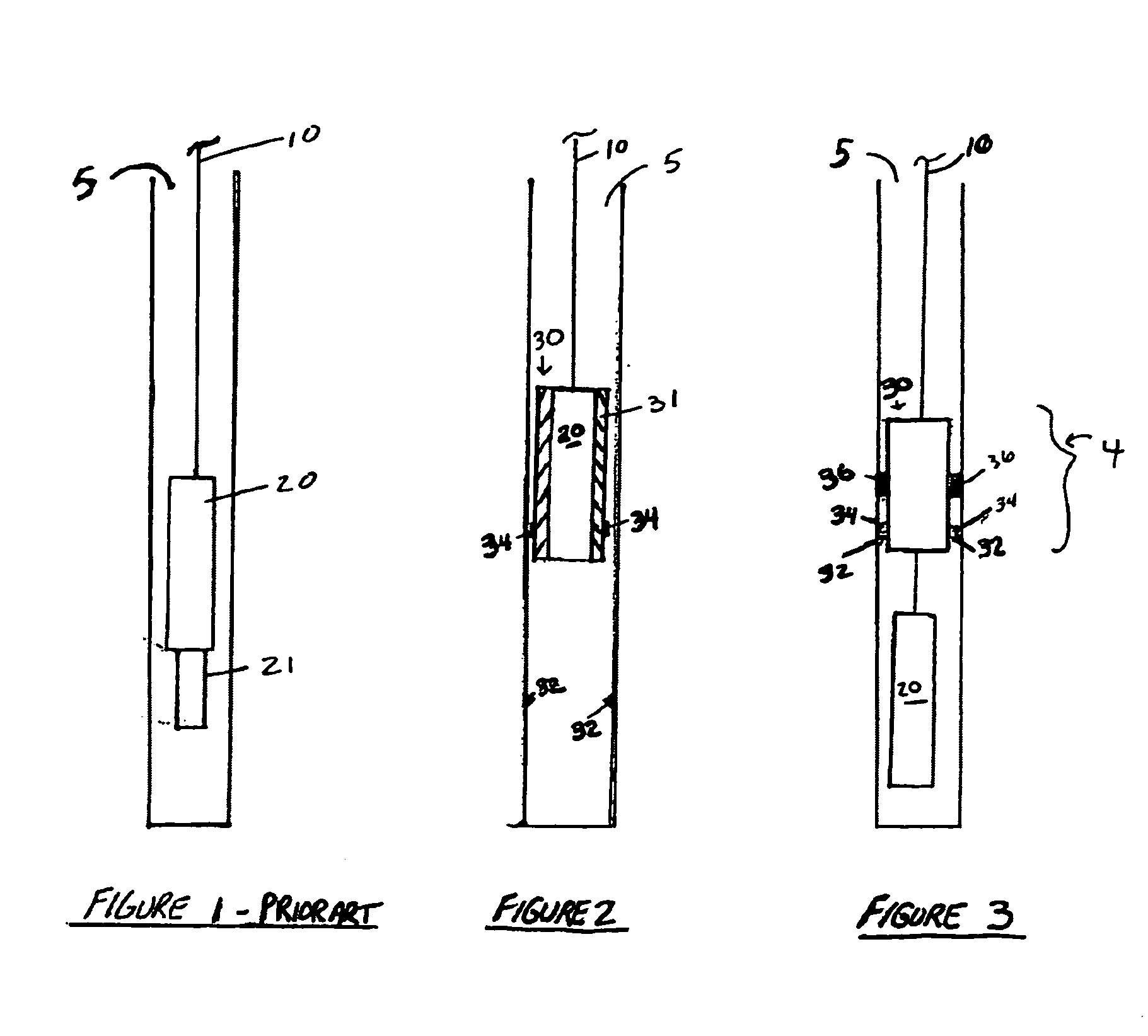
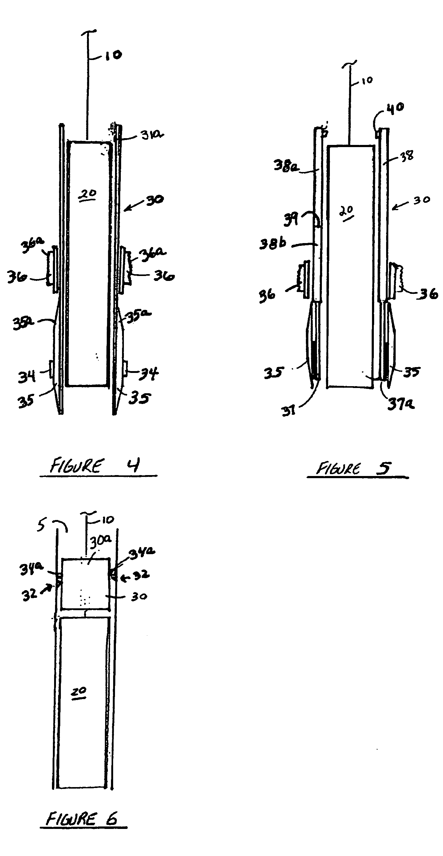
[0033] With reference to the drawing herein, one embodiment of a modular weight bar 30 for use with a downhole tool 20 is shown in FIG. 2. This embodiment of the modular weight bar 30 comprises a body 31 formed to receive a downhole tool 20 within the body 31 and a deployment system that provides for releaseable attachment of the modular weight bar 30 to the downhole tool 20. In the embodiment of FIG. 2, the modular weight bar 30 provides added mass to the downhole tool 20 so the combination downhole tool 20 and modular weight bar 30 can be lowered into a pressurized wellbore on a wireline 10. To accommodate the wireline 10 the modular weight bar 30 should incorporate an opening 44 at its top that is substantially coaxial to the body of the modular weight bar 30. The modular weight bar 30 also works to house and protect the downhole tool 20 with its sleevelike configuration. Formed on the outer surface of the body 31 is at least one latch tab 34 situated to contact at least one prot...


PUM


Abstract

A modular weight bar usable in conjunction with downhole tools disposed within a pressurized wellbore. The modular weight bar adds mass to the downhole tool so it can be suspended and lowered within the pressurized wellbore on wireline. The modular weight bar is separatable from the downhole tool at a selected depth within the wellbore thereby allowing the downhole tool to be further lowered within the wellbore without being accompanied by the weight bar.

Description

RELATED APPLICATIONS [0001] This application claims priority from co-pending U.S. Provisional Application No. 60 / 441,007, filed Jan. 17, 2003, the full disclosure of which is hereby incorporated by reference herein.BACKGROUND OF THE INVENTION [0002] 1. Field of the Invention [0003] The invention relates generally to the field of exploration and production of hydrocarbons from wellbores. More specifically, the present invention relates to a method and apparatus to operate wireline tools within a pressurized wellbore with increased effectiveness and at a greater wellbore depth. Yet even more specifically, the present invention relates to a method and apparatus to operate wireline tools within a pressurized wellbore having a releasably attached weight bar that is selectively removable at a specified depth within the wellbore. [0004] 2. Description of Related Art [0005] Often the pressure within a wellbore exceeds the ambient pressure at the surface of the wellbore. Thus, when objects s...

Claims


Application Information

Patent Timeline
IPC IPC(8): E21B23/02E21B23/04E21B23/14E21B47/01
CPCE21B23/02E21B47/011E21B23/14E21B23/04E21B47/017E21B23/0412
Inventor WILLS, PHILIP
Owner BAKER HUGHES INC
Why Eureka
Eureka Blog
Learn More