Anchorless electrostatically activated micro electromechanical system switch

an electrostatic activation and micro-electromechanical technology, applied in the field of switches, can solve the problems of slow switching speed, relatively high actuation voltage, and none of the above features of conventional switches

Inactive Publication Date: 2005-03-31
NORTHROP GRUMMAN SYST CORP
View PDF5 Cites 80 Cited by
  • Summary
  • Abstract
  • Description
  • Claims
  • Application Information

AI Technical Summary

Benefits of technology

[0008] Accordingly, the present invention provides a micro electromechanical system (MEMS) switch that includes a substrate and a stress free beam disposed above the substrate. The stress free beam is provided within first and second platforms. The first and second platforms are disposed on the substrate and limit displacement of the stress free beam in directions that are not substantially parallel to the substrate. The MEMS switch also includes a first set of one or more control pads disposed in a vicinit

Problems solved by technology

However, none of the conventional switches exhibit all of the above features.
However, electrostatic switches also have several disadvantages such as slow switching speed (on the order of psec to msec), relatively high actuation voltage (1

Method used


Image

  • Anchorless electrostatically activated micro electromechanical system switch
  • Anchorless electrostatically activated micro electromechanical system switch
  • Anchorless electrostatically activated micro electromechanical system switch

Examples


Embodiment Construction

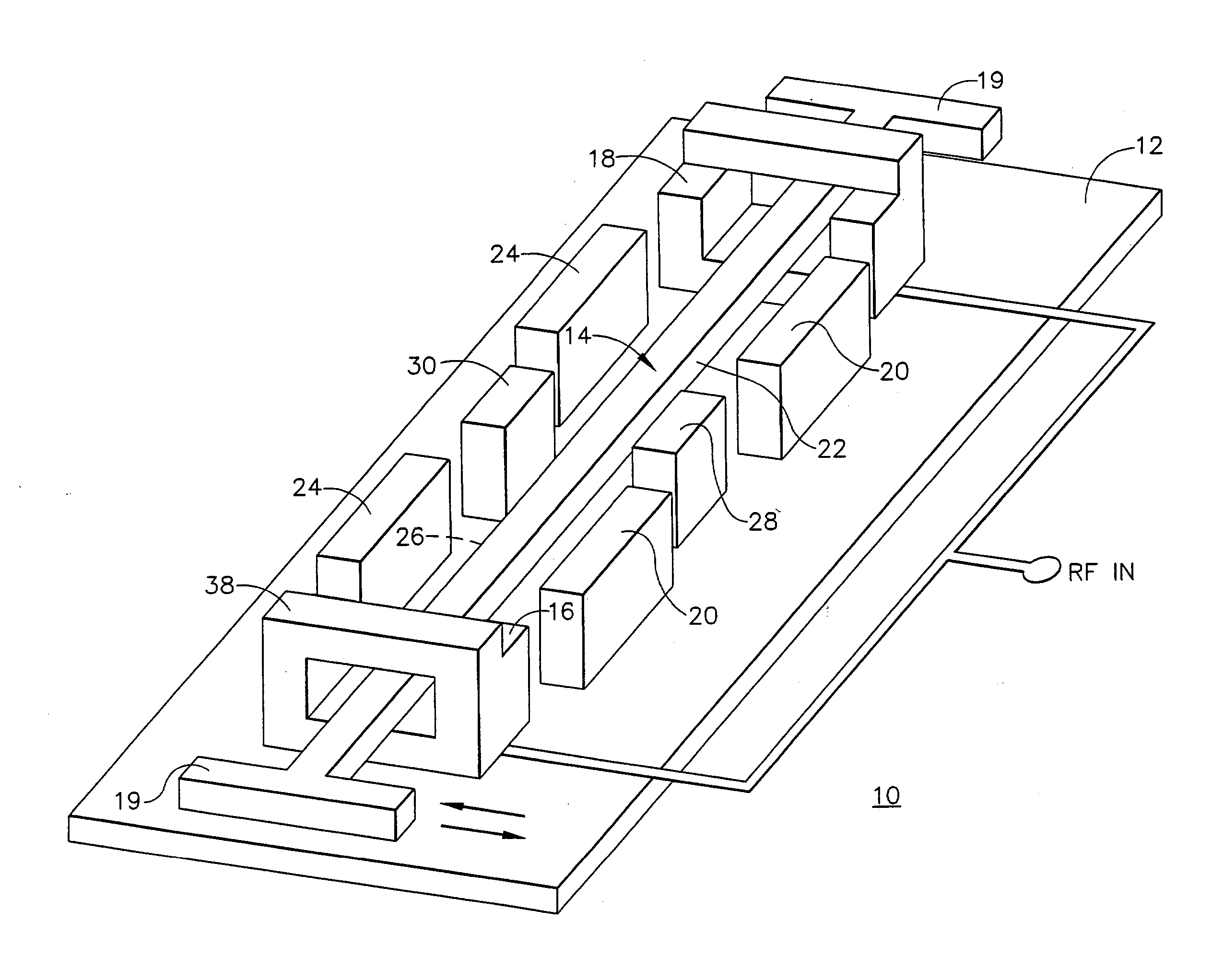
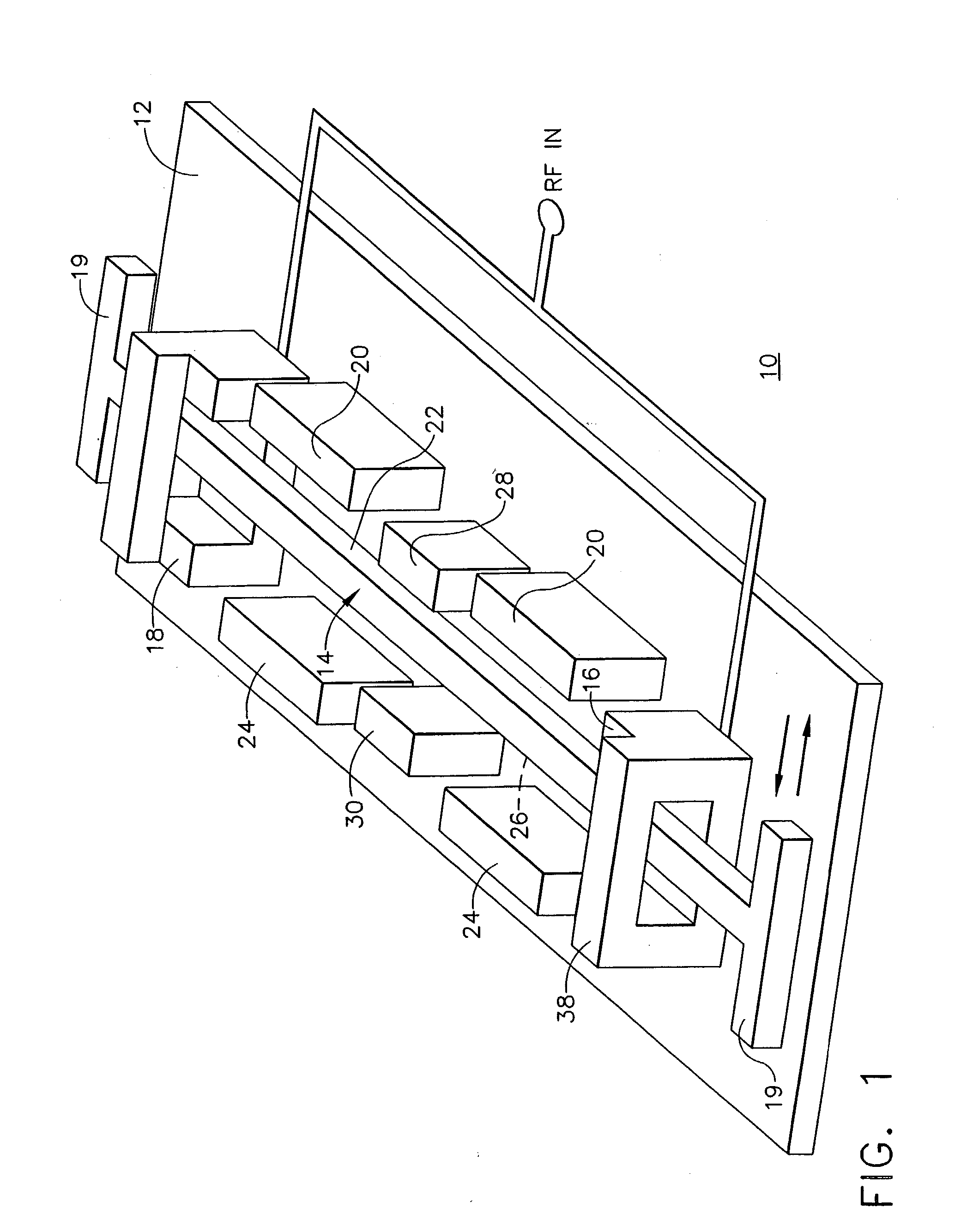
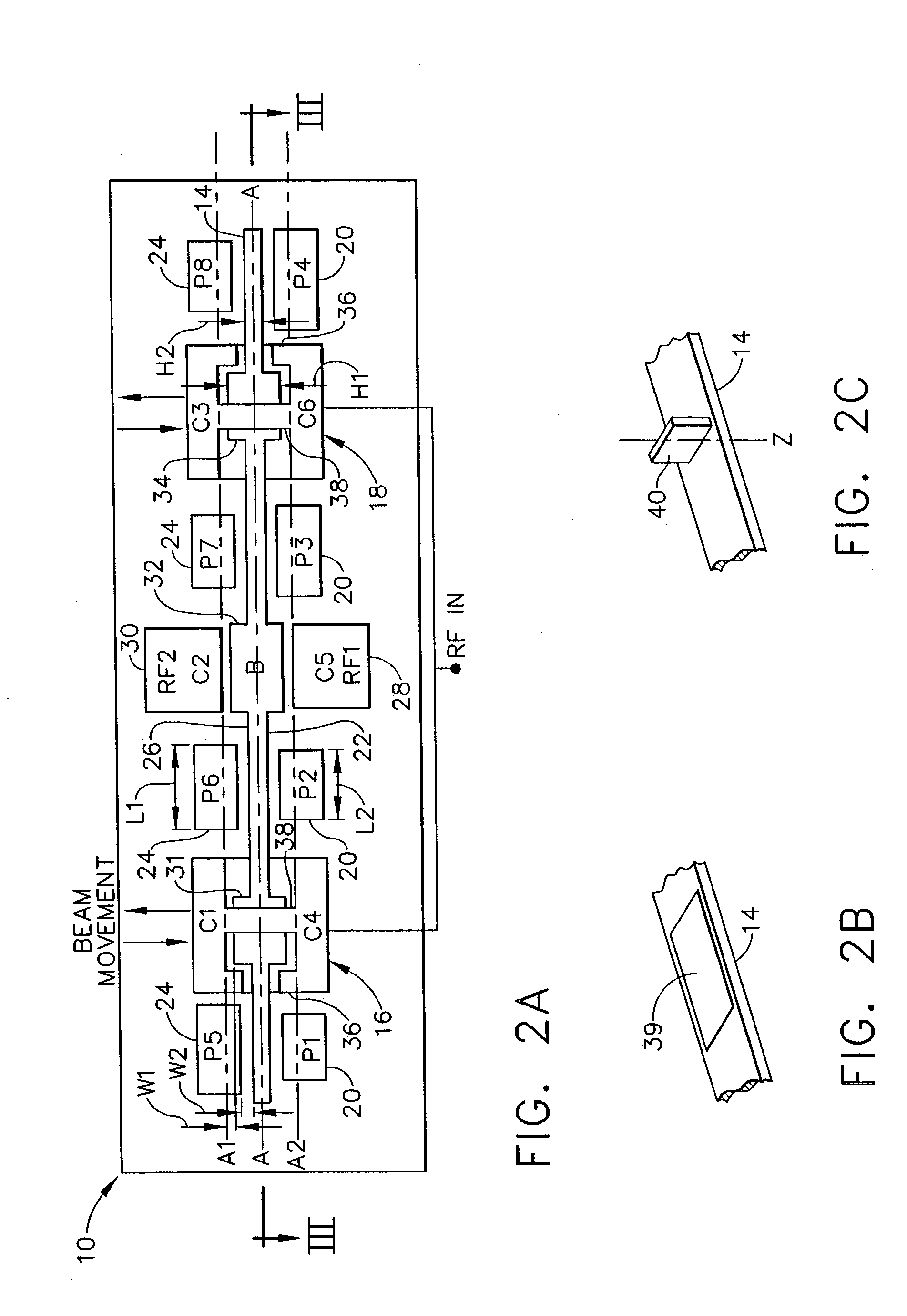
[0024] Referring now to the drawings in which like numerals reference like parts, FIGS. 1-2A show an exemplary MEMS switch 10 according to a first preferred embodiment. Referring to FIG. 1, the MEMS switch 10 includes a substrate 12 such as, for example, GaAs, quartz, or lithium niobate. However, the substrate 12 may also be transparent depending on the particular application intended for the MEMS switch 10. A beam 14 (stress free beam) is disposed above the substrate 12 and is provided within a first platform 16 and a second platform 18. The first and second platforms 16, 18 are also disposed on the substrate 12. The stress free beam 14 is not anchored to the first platform 16 or the second platform 18. Hence, the beam 14 is stress free and is therefore referred to as a “stress free beam.”

[0025] The stress free beam 14 is manufactured from a highly conductive material such as, for example, gold or tungsten and is displaceable in directions substantially parallel to the substrate 12...


PUM


Abstract

A micro electromechanical system (MEMS) switch (10) includes a substrate (12) and a stress free beam (14) disposed above the substrate (12). The stress free beam (14) is provided within first and second platforms (16, 18) to limit displacement of the stress free beam (14) in directions that are not substantially parallel to the substrate (12). A set of one or more control pads (20) is disposed in a vicinity of a first lengthwise side (22) of the stress free beam (14) for creating a potential on the first lengthwise side (22) of the stress free beam (14). The stress free beam (14) is displaceable in directions substantially parallel to the substrate (12) in accordance with the potential for providing a signal path.

Description

FIELD OF THE INVENTION [0001] The present invention relates generally to switches and, more specifically, to switches implemented by Micro Electromechanical System (MEMS) technology. BACKGROUND [0002] Micro Electromechanical System (MEMS) switches are widely used in RF communication systems such as, for example, phased array antennas, phase shifters, switchable tuning elements, and radar sensors. Generally, MEMS switches have features such as low insertion loss, low power consumption, low cost, small size, wide bandwidth operation, long lifetimes and fast switching speeds not found in conventional solid state switches (e.g., FETs or PIN diodes). Specifically, a high quality MEMS switch should ideally have as many of the following features as possible: low activation voltage, high switching speed, long operation lifetime, good isolation from the output signal during an OFF state, low contact resistance and high contact force between the contact electrodes during an ON state, little o...

Claims


Application Information

Patent Timeline
IPC IPC(8): G02B26/08B81B5/00H01H9/40H01H59/00
CPCG02B26/0841H01H2001/0078H01H59/0009H01H9/40B81B5/00B81B2201/018H01H59/00
Inventor YIP, DAVID
Owner NORTHROP GRUMMAN SYST CORP
Why Eureka
Try Eureka