Panoramic scanner

a scanner and panoramic technology, applied in the field of three-dimensional detection of objects, can solve the problems of high procurement cost, insufficient correspondence between computer model and real object, and high cost of laser scanners, and achieve the effect of simple and cost-effective manner

Inactive Publication Date: 2005-03-31
SIEMENS AUDIOLOGISCHE TECHN
View PDF8 Cites 54 Cited by
  • Summary
  • Abstract
  • Description
  • Claims
  • Application Information

AI Technical Summary

Benefits of technology

[0009] It is an object of the present invention to provide a method and also a panoramic scanner which make it possible to detect three-dimensionally an object, in particular an ear impression, in a comparatively simple and cost-effective manner with the accuracy required for producing a hearing aid housing shell.

Problems solved by technology

What is disadvantageous about the known laser scanners is their high procurement costs, which are occasionally also caused by the high-precision mechanism of the rotary stage controllers.
What is disadvantageous about the known method is (for some applications) the inadequate correspondence between the computer model and the real object.
This saves time and costs in the production of a hearing aid housing.

Method used


Image

  • Panoramic scanner
  • Panoramic scanner
  • Panoramic scanner

Examples


Embodiment Construction

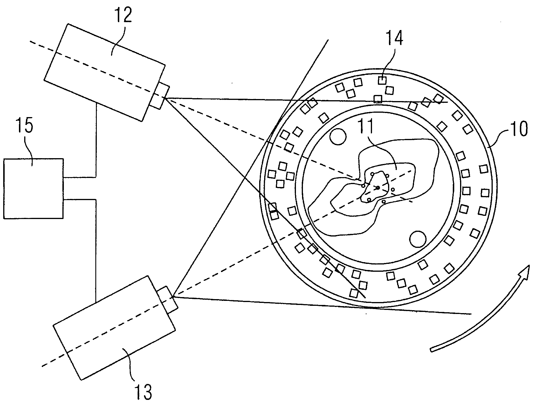
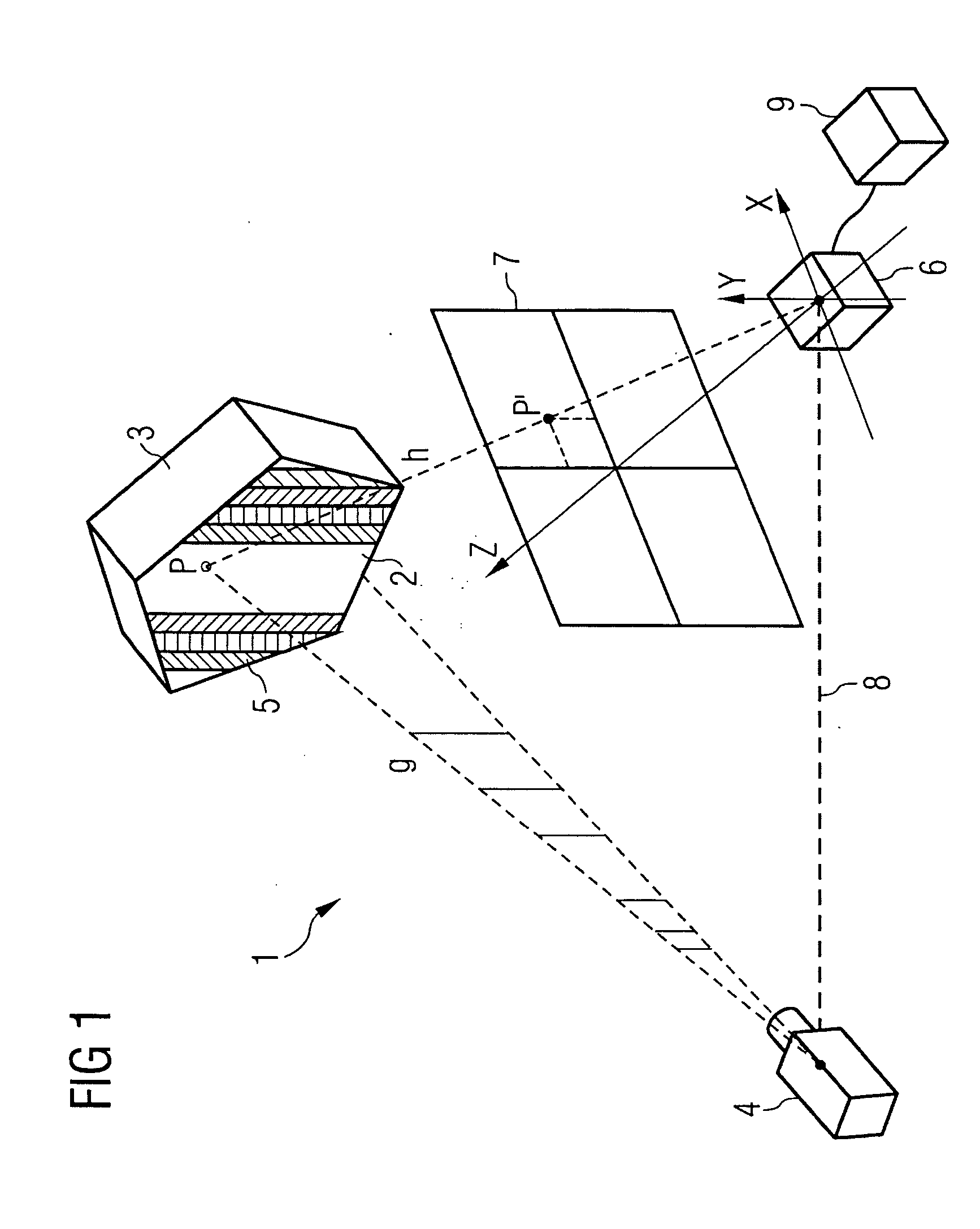
[0034]FIG. 1 illustrates an apparatus 1 which serves for determining the three-dimensional object coordinates of a surface 2 of an object 3 to be detected.

[0035] The apparatus 1 has a projector 4, which projects a color pattern 5 onto the surface 2 of the object 3 to be detected. In the case illustrated in FIG. 1, the color pattern 5 is composed of a series of color stripes lying next to one another. However, it is also conceivable to use a two-dimensional color pattern instead of the one-dimensional color pattern 5 illustrated in FIG. 1.

[0036] In the case of the exemplary embodiment illustrated in FIG. 1, a projection plane g may be assigned to each point P of the surface 2 of the object 3. Consequently, projection data are coded by the color pattern 5. The color pattern 5 projected onto the surface 2 of the object 3 is converted into an image 7 by a camera 6 in that the point P on the surface 2 is transformed into the point P′ in the image 7. Given a known arrangement of the pro...


PUM


Abstract

A cost-effective panoramic scanner provides for the three-dimensional detection of objects, and in particular for the detection of ear impressions. For this purpose, a pattern is projected onto an object to be detected via a projector that generates an object image via a camera, the object image containing images of markings that enable an unambiguous assignment of the position of the object with respect to the projector and the camera. Since an exact synchronization of the rotary movement of the object with the recording of the object images is not necessary by virtue of the markings, the precision of the mechanism used is relatively nonstringent.

Description

CROSS-REFERENCE TO RELATED APPLICATIONS [0001] The present application claims the benefit of U.S. Provisional Application No. 60 / 505,911, filed Sep. 25, 2003, herein incorporated by reference.BACKGROUND OF THE INVENTION [0002] The invention relates to a method for the three-dimensional detection of an object. Furthermore, the invention relates to an apparatus for performing the method and a use of the apparatus and the method. [0003] Methods for the three-dimensional detection and digitization of objects are used for various application purposes, e.g., in the development, production and quality control of industrial products and components. In medical technology, use is made of, for example, optical measurement methods for producing the housings of hearing aids that can be worn in the ear. [0004] For the purpose of individually adapting a housing to the auditory canal of a person wearing a hearing aid, impressions of the patient's outer auditory canal are created by an audiologist b...

Claims


Application Information

Patent Timeline
Patent Type & Authority Applications(United States)
IPC IPC(8): A61B5/107G01B11/25
CPCA61B5/0064G01B11/2522G01B11/2509A61B5/1077
Inventor DOEMENS, GUNTERFORSTER, FRANKNIEDERDRANK, TORSTENRUMMEL, PETER
Owner SIEMENS AUDIOLOGISCHE TECHN
Why Eureka
Try Eureka