Power output stage, method for operation

a technology of power output stage and power output stage, which is applied in the direction of pulse technique, dynamo-electric converter control, instruments, etc., can solve the problem that the form of short-circuit detection cannot be carried out in a power output stage, and achieve the effect of simple and cost-effectiv

Inactive Publication Date: 2015-06-18
ROBERT BOSCH GMBH
View PDF8 Cites 3 Cited by
  • Summary
  • Abstract
  • Description
  • Claims
  • Application Information

AI Technical Summary

Benefits of technology

[0004]The power output stage according to the invention has the advantage that a short-circuit detection can be carried out without starting up the electrical machine and in a simple and cost effective manner. The power output stage according to the invention provides for the control unit to have a controllable first pull-up apparatus and a controllable first pull-down apparatus for a first of the half-bridges and a controllable second pull-up apparatus and a controllable second pull-down apparatus for a second of the half-bridges, the control unit actuating the semiconductor switches, the pull-up apparatuses and the pull-down apparatuses in a short-circuit test mode in order to detect a short-circuit current. The power output stage is thus characterized by pull-up and pull-down apparatuses which can be used to pull the respective half-bridge to the voltage level of the supply line or to the...

Problems solved by technology

The disadvantage thereby is that this form of short-circuit detection ca...

Method used


Image

  • Power output stage, method for operation
  • Power output stage, method for operation

Examples


Embodiment Construction

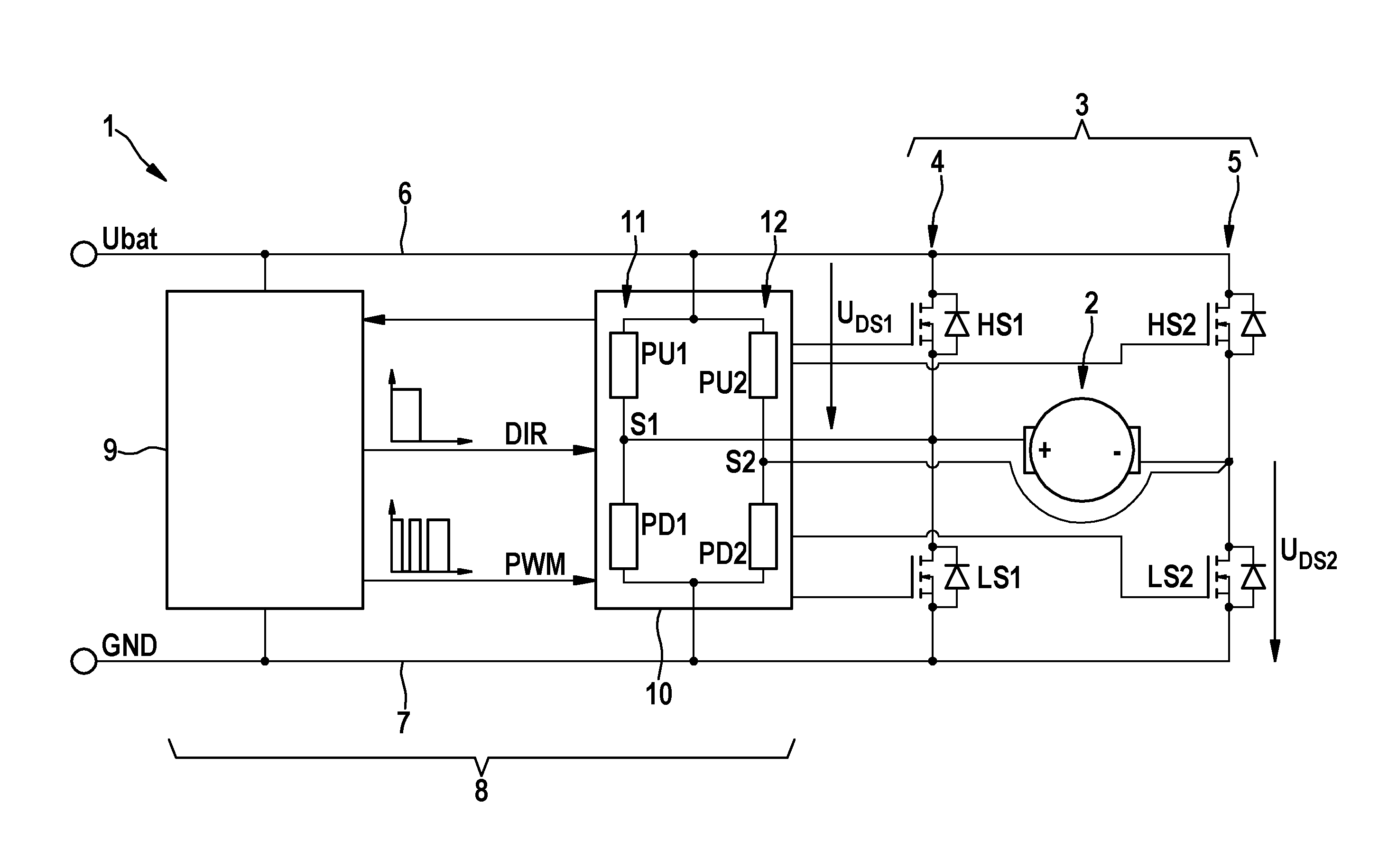
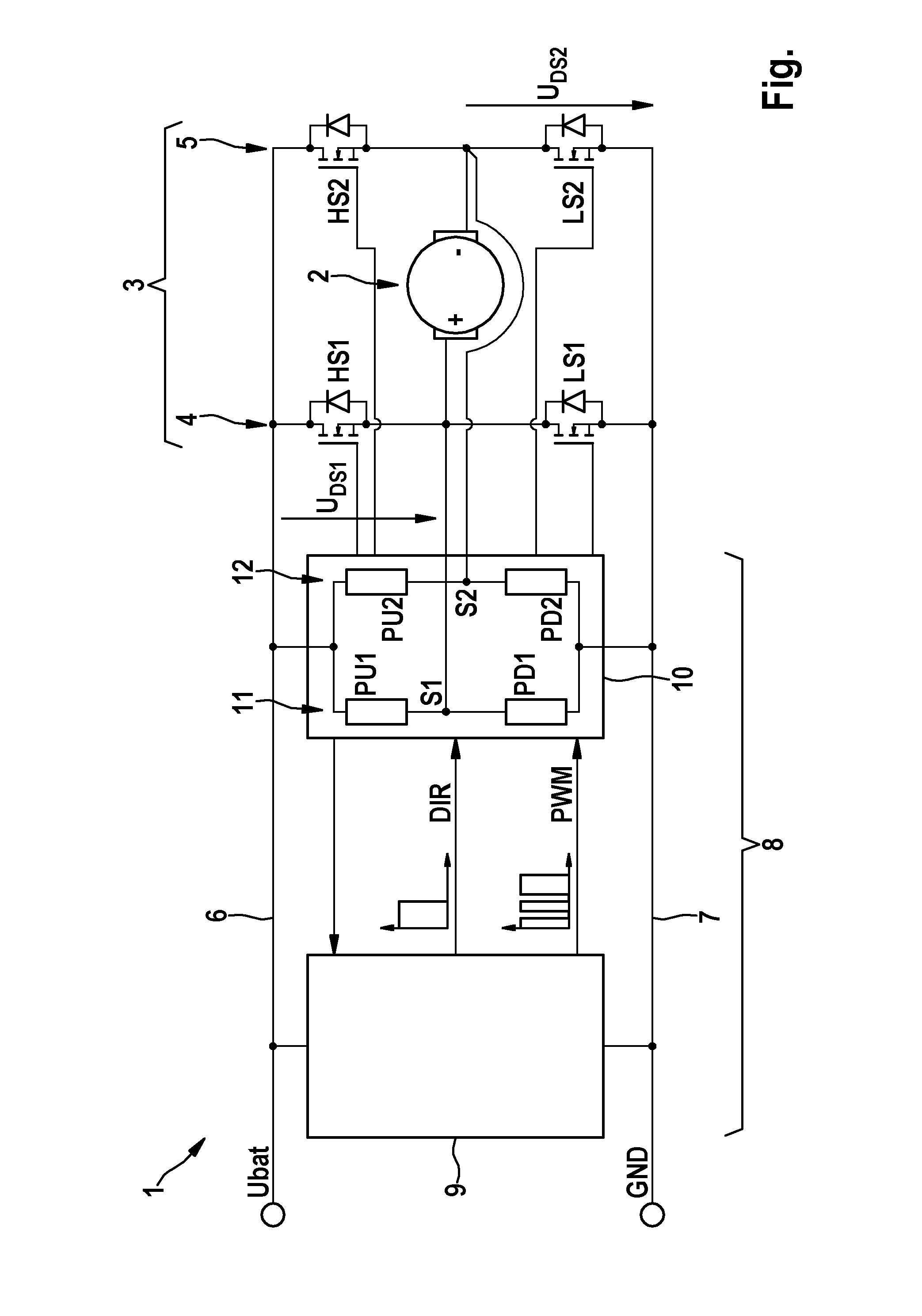
[0018]The FIGURE shows a schematic diagram of a power output stage 1 in a simplified depiction, said power output stage being designed to drive an electrical machine 2. To this end, the power output stage 1 comprises a bridge circuit 3 which in the present example is designed as an H bridge circuit and has accordingly two half-bridges 4 and 5. The half-bridges 4 and 5 are connected between a supply line 6, which is / can be connected to a power source and therefore has a voltage Ubat, and an earth line. Each of the half-bridges 4 has two semiconductor switches HS1 and LS1 or, respectively, HS2 and LS2, from which respectively one switch is provided as a high-voltage side semiconductor switch HS1, HS2 and the other as a low-voltage side semiconductor switch. The semiconductor switches HS1, HS2, LS1, LS2 are in each case designed as MOSFET switching elements and are connected to a control unit 8 which actuates said semiconductor switches HS1, HS2, LS1, LS2 in a clocked manner by means o...


PUM


Abstract

The invention relates to a power output stage (1), in particular for a controller of an electrical machine (2) for a motor vehicle, comprising at least one control unit (8) and comprising at least four semiconductor switches (HS1, HS2, LS1, LS2) which can be individually actuated by the control unit (8) and which are connected to at least two half-bridges (4, 5) for operating the electrical machine (2) in order to form a bridge circuit (3), and are connected to a supply line (6) and an earth line (7) of the power output stage (1). Provision is made for the control unit (8) to have a controllable first pull-up apparatus (PU1) and a controllable first pull-down apparatus (PD1) for a first of the half-bridges (4) and a controllable second pull-up apparatus (PU2) and a controllable second pull-down apparatus (PD2) for a second of the half-bridges (5), the control unit (8) actuating the semiconductor switches (HS1, HS2, LS1, LS2) the pull-up apparatuses (PU1, PU2) and the pull-down apparatuses (PD1, PD2) in a short-circuit test mode in order to detect a short-circuit current.

Description

BACKGROUND OF THE INVENTION[0001]The invention relates to a power output stage, in particular for a controller of an electrical machine for a motor vehicle, comprising at least one control unit and comprising at least four semiconductor switches which can be individually actuated by the control unit and which are connected to at least two half-bridges for operating the electrical machine in order to form a bridge circuit, and are connected to a supply line and an earth line of the power output stage.[0002]The invention further relates to a method for operating such a power output stage.[0003]Power output stages as well as a method for operating the same are known from the technical field. In order to drive electrical machines, so-called clocked output stages or power output stages are frequently used which actuate the electrical machine by means of semiconductor switches that are interconnected in a bridge circuit. A constant supply d. c. voltage can be converted into a variable ope...

Claims


Application Information

Patent Timeline
IPC IPC(8): H02P6/14G01R31/02H02P31/00G01R31/50
CPCH02P6/14G01R31/025H02P31/00G01R31/40H02H7/0844H03K17/08142H03K17/18H03K2217/0027H03K2217/0045B60L3/003B60L2240/526B60L2240/529B60L2240/547G01R31/50
Inventor FORSCHT, MICHAELRUMMEL, MICHAELSCHULZE-LCKING-KONERT, GEORG
Owner ROBERT BOSCH GMBH
Why Eureka
Try Eureka