Apparatus for reshaping an optical beam bundle

a bundle and optical beam technology, applied in optics, condensers, instruments, etc., can solve the problems of unconditioned output laser beams that are rarely adapted for particular applications, laser beams that suffer most from lack of brightness, etc., to reduce output beam divergence and/or total cross-sectional area, and increase laser beam brightness

Inactive Publication Date: 2005-03-31
INSTITUT NATIONAL D'OPTIQUE
View PDF3 Cites 32 Cited by
  • Summary
  • Abstract
  • Description
  • Claims
  • Application Information

AI Technical Summary

Benefits of technology

[0004] In this way, the second optical beam bundle can be more adapted for a particular application. In certain cases, this also achieves increased brightness of a laser beam through reduced output beam divergence and / or total cross-sectional area.

Problems solved by technology

One major difficulty in using laser diode bars and other systems is that the unconditioned output laser beam is rarely adapted for the particular application.
Another problem is that the laser beam most often suffers from a lack of brightness.

Method used


Image

  • Apparatus for reshaping an optical beam bundle
  • Apparatus for reshaping an optical beam bundle
  • Apparatus for reshaping an optical beam bundle

Examples


Embodiment Construction

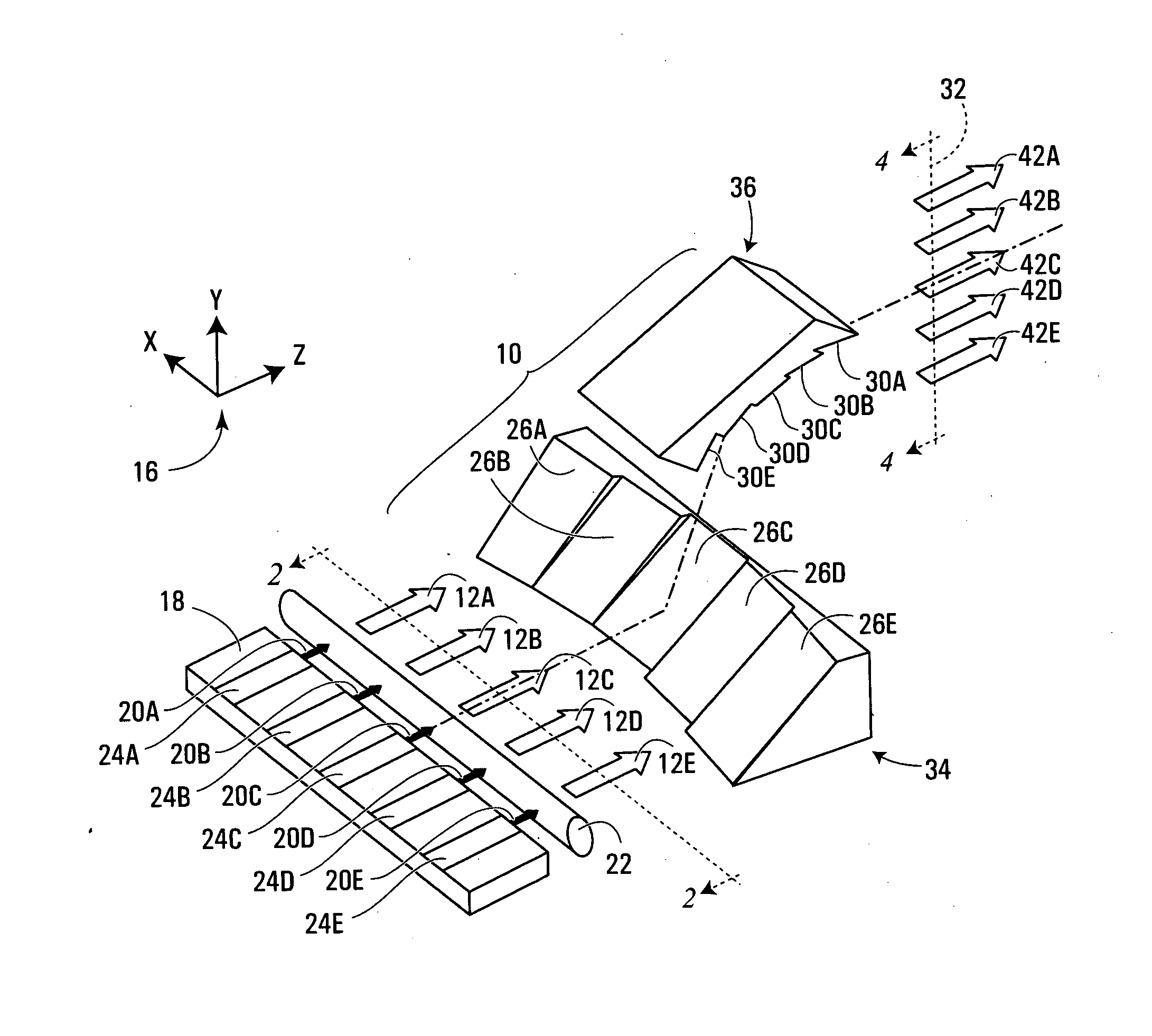
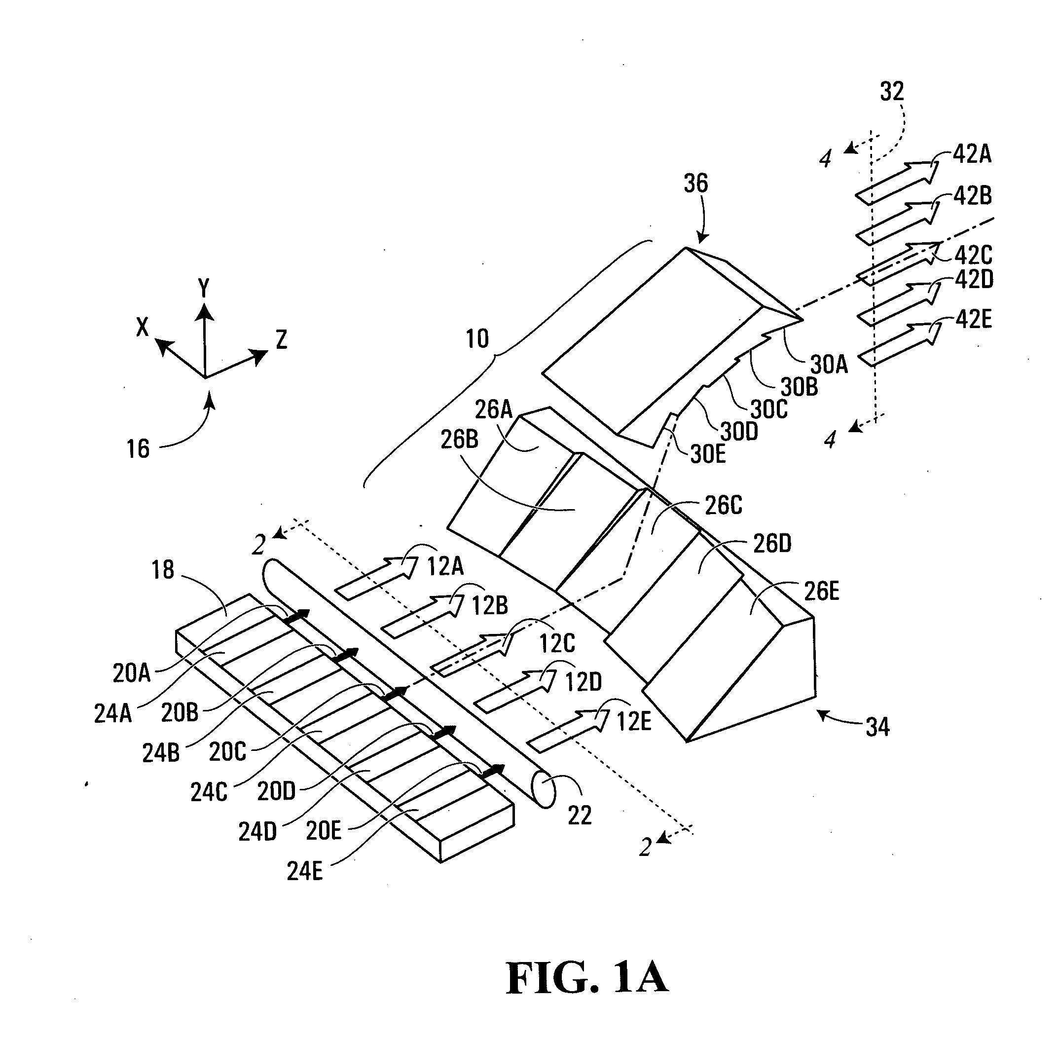
[0029] In FIGS. 1A through 7B, a three-dimensional orthogonal reference system 16 with three directions (axes) x, y and z has been defined for the purposes of convenience. As seen inFIG. 1A, an optical emitter 18 (e.g., a laser diode bar) emits a plurality of beamlets 20a-e travelling generally in the z-direction of the orthogonal reference system 16, within a common x-z plane. In different embodiments, the beamlets 20a-e may all have the same wavelength, or they may each have different wavelengths, or they may each occupy a range of wavelengths.

[0030] Despite travelling generally in the z-direction, the beamlets 20a-e emitted by the emitter 18 are typically divergent in the y-direction and also, although somewhat less strongly, in the x-direction. Accordingly, beam-collimating optics 22 may be provided for reducing the divergence of the plurality of beamlets 20a-e, resulting in the creation of respective input optical beams 12a-e forming part of an input optical beam bundle. Toget...


PUM


Abstract

Apparatus for shaping an optical beam bundle carrying a plurality of substantially parallel optical beams disposed in a common plane of travel. First reflective facets and second reflective facets are provided, the first reflective facets being oriented so as to deflect the optical beams of the bundle into a plurality of intermediate, substantially non-parallel optical beams. Each of the second reflective facets is spatially disposed so as to receive a respective one of the intermediate optical beams at a different respective distance from the plane of travel of the optical beam bundle. Also, the second reflective facets are oriented so as to deflect the intermediate optical beams into a bundle of substantially parallel output optical beams. In this way, the output beam can be more adapted for a particular application. In certain cases, this also achieves increased brightness of a laser beam through reduced output beam divergence and / or total cross-sectional area.

Description

FIELD OF THE INVENTION [0001] The present invention relates generally to optical devices and components and, more particularly, to optical devices and components for reshaping bundles or arrays of optical beams. BACKGROUND OF THE INVENTION [0002] In recent years, laser diode systems such as laser diode bars have been in use in various applications such as machining of materials, treatment of surfaces, and illumination and pumping of solid-state lasers. These various applications have different requirements on the laser beam characteristics, such as the beam shape, brightness and divergence. One major difficulty in using laser diode bars and other systems is that the unconditioned output laser beam is rarely adapted for the particular application. Another problem is that the laser beam most often suffers from a lack of brightness. Therefore, laser beam conditioning and / or reshaping is required in order to optimize the output laser beam characteristics. SUMMARY OF THE INVENTION [0003]...

Claims


Application Information

Patent Timeline
Patent Type & Authority Applications(United States)
IPC IPC(8): G02B27/09
CPCG02B27/0977G02B19/0028G02B19/0057
Inventor GRENIER, PAULTAILLON, YVES
Owner INSTITUT NATIONAL D'OPTIQUE
Why Eureka
Try Eureka