Magnetic head and method of manufacturing same, head suspension assembly and magnetic disk apparatus
a technology of magnetic head and suspension assembly, which is applied in the direction of nanomagnetism, data recording, instruments, etc., can solve the problems of low resistance of the whole magneto-resistive device, few opportunities for oxygen to bind, and relatively large variation in the resistance of the magneto-resistive device to achieve the effect of high stability of characteristics
- Summary
- Abstract
- Description
- Claims
- Application Information
AI Technical Summary
Benefits of technology
Problems solved by technology
Method used
Image
Examples
first embodiment
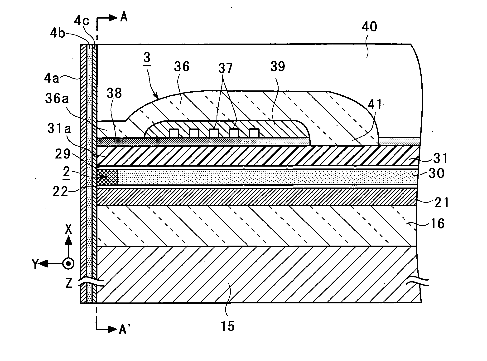
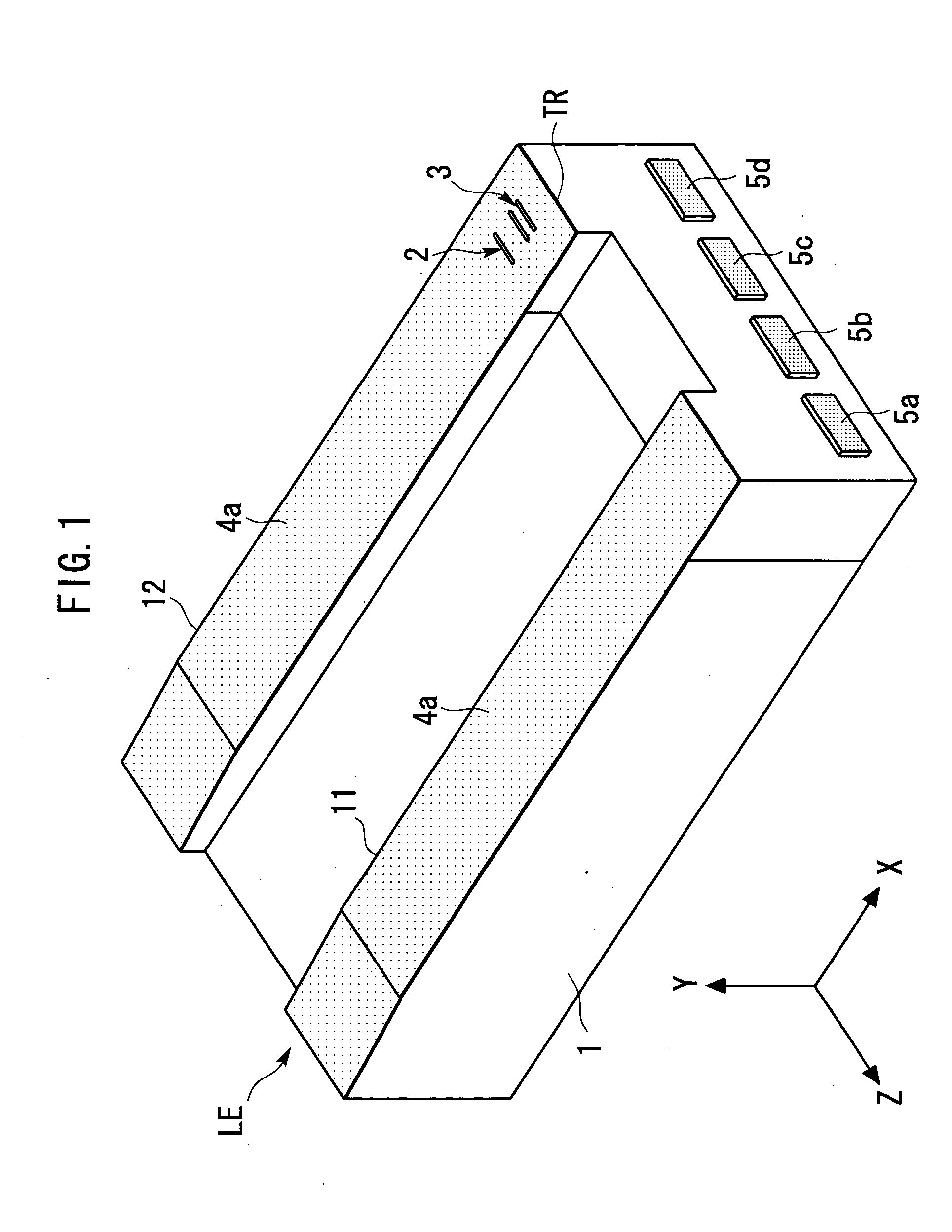
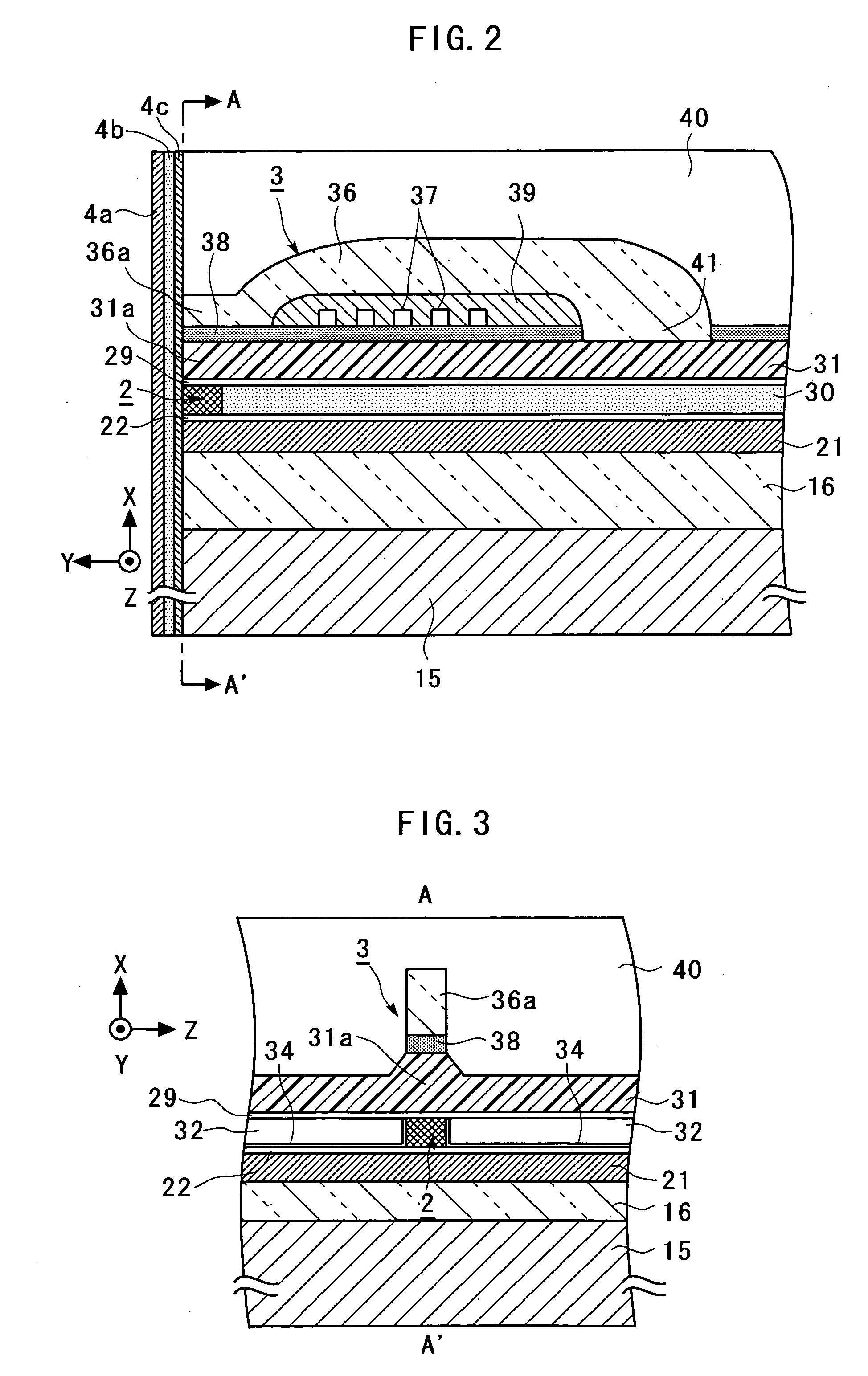
[0064] First, a magnetic head according to the present invention will be described with reference to FIGS. 1 to 5.
[0065]FIG. 1 is a general perspective view schematically illustrating the magnetic head according to the first embodiment of the present invention. FIG. 2 is an enlarged cross-sectional view schematically illustrating a portion of a TMR device 2 and an inductive magnetic transducing device 3 in the magnetic head illustrated in FIG. 1. FIG. 3 is a general sectional view taken along a line A-A′ indicated by arrows in FIG. 2. FIG. 4 is a further enlarged view illustrating around the TMR device 2 in FIG. 2. FIG. 5 is a further enlarged view around the TMR device 2 in FIG. 3. For facilitating the understanding, an X-axis, a Y-axis and a Z-axis, orthogonal to one another, are defined as shown in FIG. 1 to 5 (the same applies to figures later described). The Z-axis direction indicated by the arrow is referred to as the “+Z-direction” or “+Z-side,” and the opposite direction is ...
third embodiment
[0118] Subsequently, in the third embodiment, after the bar 102 is once left in the atmosphere, the bar 102 is etched for cleaning the surface and the like by dry etching such as sputter etching, ion beam etching or the like in the same vacuum chamber in which the variation reducing layer 4c is deposited.
[0119] Next, ion beam deposition or sputtering is performed using an oxide of a metal or a semiconductor (for example, Al, Si, Ti, V, Cr, Mn, Fe, Ni, Co, Cu, Zn, Zr, Nb, Mo, Hf, Ta, or W) as a target without using oxygen for a process gas to deposit the variation reducing layer 4c on the surface of the bar 102 on the ABS side.
[0120] Next, after the bar 102 is etched for cleaning the surface and the like by dry etching such as sputter etching, ion beam etching or the like in the same vacuum chamber in which the variation reducing layer 4c has been deposited, the underlying layer 4b made, for example, of Si is deposited on the variation reducing layer 4c by a sputtering method or the...
fourth embodiment
[0130] Next, a magnetic head according to the present invention will be described with reference to FIG. 16.
[0131]FIG. 16 is an enlarged cross-sectional view schematically illustrating a main portion of a magnetic head according to a fourth embodiment of the present invention, and corresponds to FIG. 4. In FIG. 16, components identical or corresponding to those in FIG. 4 are designated by the same reference numerals, and repetitive description thereon is omitted.
[0132] The magnetic head according to the fourth embodiment differs from the magnetic head according to the first embodiment only in the composition of the variation reducing layer 4c. In the first embodiment, the variation reducing layer 4c is made of the same material in any part thereof. In the fourth embodiment, on the other hand, respective portions 21a, 22a, 24a-29a, 31a of the variation reducing layer 4c which cover the layers 21, 22, 24-29, 31, respectively, are made of materials which are determined in accordance w...
PUM
| Property | Measurement | Unit |
|---|---|---|
| thickness | aaaaa | aaaaa |
| pressure | aaaaa | aaaaa |
| accelerating current | aaaaa | aaaaa |
Abstract
Description
Claims
Application Information
 - R&D
- Intellectual Property
- Life Sciences
- Materials
- Tech Scout
- Unparalleled Data Quality
- Higher Quality Content
- 60% Fewer Hallucinations
Browse by: Latest US Patents, China's latest patents, Technical Efficacy Thesaurus, Application Domain, Technology Topic, Popular Technical Reports.
© 2025 PatSnap. All rights reserved.Legal|Privacy policy|Modern Slavery Act Transparency Statement|Sitemap|About US| Contact US: help@patsnap.com


