System for overvoltage protection

a technology of overvoltage protection and surge protection, which is applied in the direction of overvoltage protection resistors, emergency protective arrangements for limiting excess voltage/current, and arrangements responsive to excess voltage, etc., can solve the problems of parasitic flash-over of charge to the electrical conductor of the power supply, power supply failure, and power supply voltage rise, etc., to achieve easy assembly, less mechanical forces, and cost-effective

Inactive Publication Date: 2005-03-31
KONINK KPN NV
View PDF4 Cites 6 Cited by
  • Summary
  • Abstract
  • Description
  • Claims
  • Application Information

AI Technical Summary

Benefits of technology

[0023] In an even further embodiment, the surge protective device of the second type is of the non blowing-off type. The surge protective device of the first type is a voltage dependent resistor or varistor and the surge protective device of the second type is a lightning current arrester or spark gap element. This arrangement assures that no hot gasses or high pressure occur, which are typical for state of the art spark gap elements which are blowing off.
[0024] The elements of the power supply unit are positioned inside a closed cabinet. This allows a small and reliable cabinet comprising the elements of the power supply (i.e., power supply connects and the protection circuitry), which is moreover cost-effective and easy to assemble. By using surge protective devices of the non blowing-off type, the cabinet will not be exposed to high internal pressures or hot gasses. This also has the added advantage that the connection between neutral conductor and surge protective device may be a short connection which results in less mechanical forces on the connections caused by strong electromagnetic fields.
[0025] The surge protective device of the second type has a rating of at least about 40 kA, more preferably at least about 50 kA and even more preferably at least about 100 kA. This will allow an effective surge protection system offering protection to currents which have been encountered in practice after lightning strikes on objects with a small foot print.

Problems solved by technology

If the charge of a lightning or of EMP strikes the cabinet in which the power supply is housed or the metal frame to which the cabinet is attached, there is a danger of parasitic flash-over of the charge to the electrical conductors of the power supply.
Since this charge is dissipated relatively poorly, the voltage in the power supply can rise to such an extent that flash-over can damage the components of the power supply, such as switches or cause failures of the power supply.
Also, other equipment of the object, such as the equipment being supplied with power may be damaged.
For such a peak voltage, a power supply for low voltage applications is not equipped.
In this known solution, however, it cannot be prevented that in the power supply substantial damage occurs when a direct lightning strike occurs on the frame, which will be further explained in the detailed description.
Moreover, mechanical damage may arise in the power supply as the large currents flowing through the conductors to be pulled from the connection points, through the electromagnetic fields caused by the large currents, as a result of which an interruption in the current flow occurs.
It need not be mentioned that, also because of the earlier mentioned periphery arrangement of the power supply and the less proper accessibility thereof, repair of the damage will take a lot of time.
As a result, the installation powered by the power supply will be out of service for a longer period of time, which leads to a higher risk of operational damage.
A disadvantage of the use of spark gap elements or spark gaps connected between the phase conductors and the neutral conductor is that a rest voltage results which is poorly defined and usually too large.
Furthermore, spark gaps will keep an undefined rest voltage, dependent on the rise time of the lightning pulse, which may be 2.5 or 4 kV, which is too high for low voltage equipment.
Also, the spark gap elements cause a short circuit and thus a net following current, which almost certainly results in breakdown of the fuses (of the electricity provider).
Breakdown of the fuses results in operational down time of the equipment supplied by the transformer.

Method used


Image

  • System for overvoltage protection
  • System for overvoltage protection
  • System for overvoltage protection

Examples


Embodiment Construction

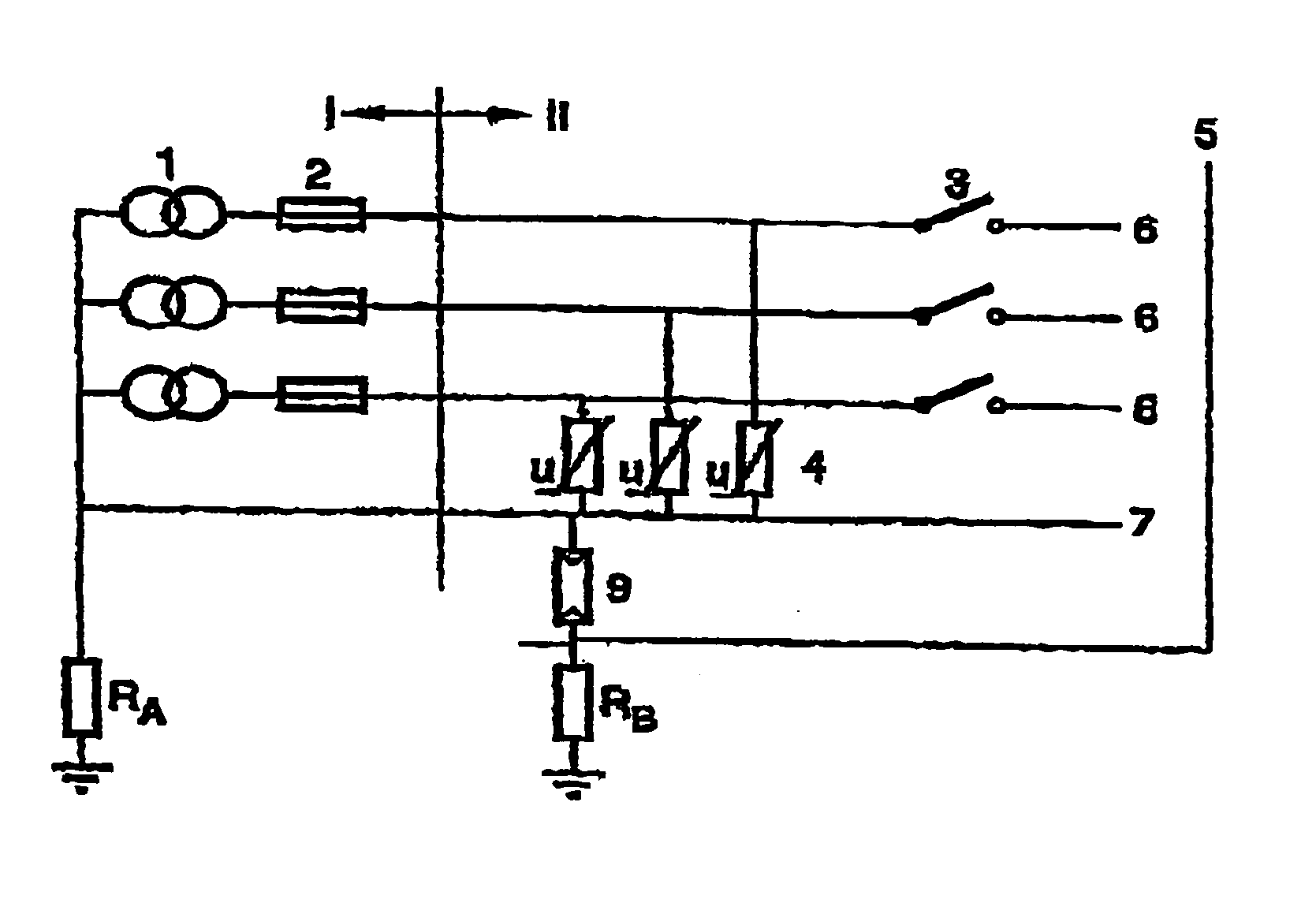
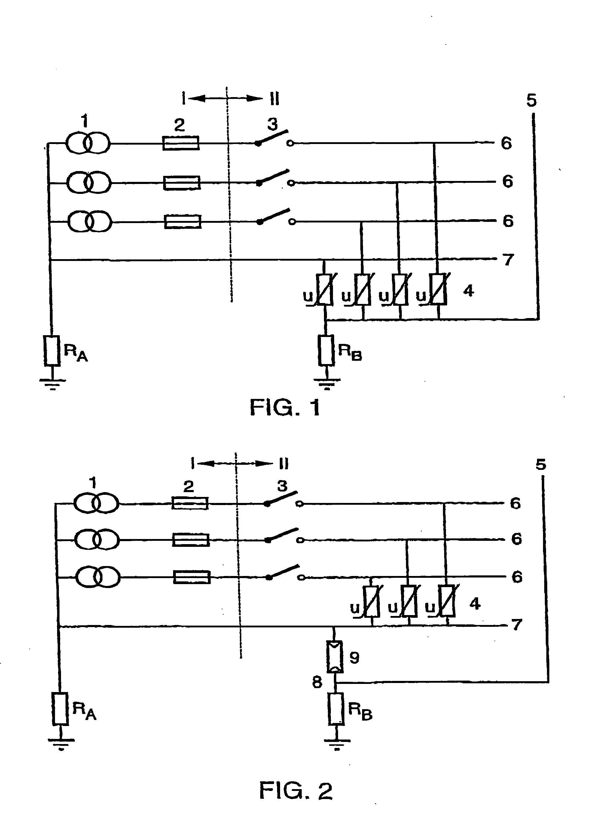
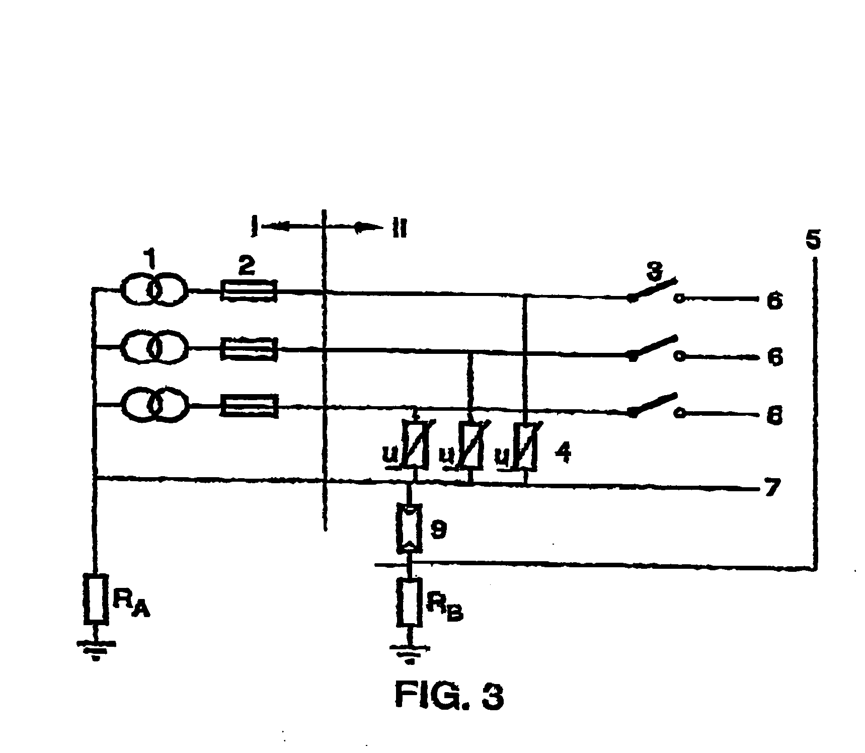
[0032] In FIG. 1, which shows the state of the art, I indicates the part which is positioned in the space of the electricity supplier. Three windings of a transformer are referenced by number 1, the secondary winding of the transformer being in a star configuration of which the star point is earthed. The impedance existing between the star point and the point of the zero potential is indicated by Ra, which usually has a very low value, e.g., a 0.5 Ohm and a self inductance of e.g., 5 μH. The secondary windings of the transformer usually have a resistance value of about 0.01 Ω and a self inductance of 50 μH. In this space, also the fuses 2 are positioned.

[0033] The equipment of the user, in the part indicated with II, comprises a three phase switch 3. Each of the conductors (phase and neutral) is connected behind the switch 3 to a connection 5 via a surge arrester 4, such as a voltage dependent resistor or varistor. The connection 5 is connected to the frame of the switch closet (or...


PUM


Abstract

System for surge protection of an object comprising a supply unit, which is connected to the secondary output of an external transformer. The secondary windings of the external transformer are coupled in a star configuration, the star point of the transformer being connected to a downstream neutral conductor and an earth electrode provided near to the transformer. In the supply unit, at least one phase conductor is connected to the neutral conductor by means of a surge protective device of a first type, and the neutral conductor is connected to an earth electrode provided near to the supply unit by means of a surge protective device of a second type. The surge protective device of the first type comprises a voltage dependent resistor or varistor and the surge protective device of the second type comprises a lightning current arrester or spark gap element.

Description

CROSS-REFERENCE TO RELATED APPLICATIONS [0001] The present patent application is a continuation-in-part application of pending U.S. patent application Ser. No. 10 / 311,158, filed on Dec. 13, 2002, which is a 371 application of PCT / EP01 / 07884, filed on Jul. 9, 2001, which claims priority under 35 U.S.C. § 119(a)-(d) to Netherlands Patent Application No. 1015766, filed on Jul. 21, 2000, the full disclosures of which are incorporated herein by reference.BACKGROUND [0002] The invention relates to a system for lightning and surge protection of objects. In particular, the invention may be used as a system for lightning and surge protection for an object set up on a limited area, on the ground or on a building. Examples of such an object comprise an installation provided with an antenna, e.g. a GSM base station. [0003] Surge protection devices for electrical power supplies are generally known. The protection device according to the application may be used to protect against surges with a hi...

Claims


Application Information

Patent Timeline
Patent Type & Authority Applications(United States)
IPC IPC(8): H02H9/04H02H9/06
CPCH02H9/06H02H9/042
Inventor KOUWENHOVEN, JACOBUS THEODORUS ANTONIUSHARTMANN, MICHIEL HENRICUSKRUL, TEUNIS FRANS
Owner KONINK KPN NV
Why Eureka
Try Eureka