Outdoors self sufficient uninterruptable luminaire

a self-sufficient, uninterruptable technology, applied in the direction of lighting and heating apparatus, lighting support devices, with built-in power, etc., can solve the problems of reducing the efficiency of lighting in general

Inactive Publication Date: 2005-03-31
ERTZE ENCINAS JUAN ANTONIO +1
View PDF27 Cites 88 Cited by
  • Summary
  • Abstract
  • Description
  • Claims
  • Application Information

AI Technical Summary

Benefits of technology

[0041] According to the present invention there is provided an integrated outdoors self sufficient luminaire, weatherproof, characterized in that within the outer body are integrally housed: an array of solid state light emitting devices, a device for collecting and converting solar radiation into electrical energy, an electronic circuitry that administers the said generated electrical energy to replenish the power consumed from an accumulator during the absence of the said radiating source, an electronic circuitry that administer and control the levels of power necessary to excite the solid state light emitting devices in a programmable fashion, a structural integrated means for attaching the luminaries into a plurality of masts, and means for maintaining the temperature around the array of solid state light emitting devices at not higher ambient temperature.

Problems solved by technology

Standard column top luminaires use a discharge lamp and control apparatus, which produces light distribution in a very general and uncontrolled manner.
Lighting in general is not energy efficient as the heat generated by the lighting means is often lost to the surroundings by means of non-visible radiation.
Disadvantages include short lifetimes (most less than a few thousand hours), low efficiency (about 8-20 lumens / watt) with resultant high per-lumen energy use and life cycle cost, attraction of insects, and high heat production.
Though highly efficient and long-lived compared to the incandescent lighting technology they displaced after the second World War, they have many disadvantages compared to other lighting sources available today, including low luminous efficiency, poor color rendition, and high ultra-violet output.
Many old fixtures remain, however, and they still remain available in the homeowner market, usually in notorious and poorly shielded “barnyard” or “dusk to dawn” fixtures.
One unusual characteristic of these lamps is that they seldom “burn out,” instead fading to lower and lower outputs over years or even decades, though still consuming essentially the original amount of electrical power.
Several lighting codes prohibit their use, though with mixed effectiveness.
The technology is moribund, and not often specified for any extensive commercial or public outdoor lighting.
Disadvantages include higher initial costs compared to incandescent lamps, large lamp size, low efficiency (compared to lamp types below) and poor output maintenance, attraction of insects, and potentially hazardous mercury waste.
Disadvantages include lower efficiency and output maintenance compared to high- and low-pressure sodium, shorter lamp lifetime compared to high-pressure sodium, color changes, ultra-violet output if not adequately filtered, and potentially hazardous mercury waste.
Disadvantages include poorer color rendition than metal halide, fluorescent and incandescent, poorer output maintenance and efficiency than low-pressure sodium, and potentially hazardous mercury waste.
Disadvantages include the lack of color rendition, shorter lamp lifetime and higher lamp replacement costs compared to HPS, and large lamp size in the higher output lamps.
Since luminous tube lighting is used for applications taking advantage of the color variety and shape flexibility inherent in the technology and not for area lighting, it is not meaningful to compare its advantages and disadvantages to the lighting sources above.

Method used


Image

  • Outdoors self sufficient uninterruptable luminaire
  • Outdoors self sufficient uninterruptable luminaire
  • Outdoors self sufficient uninterruptable luminaire

Examples


Embodiment Construction

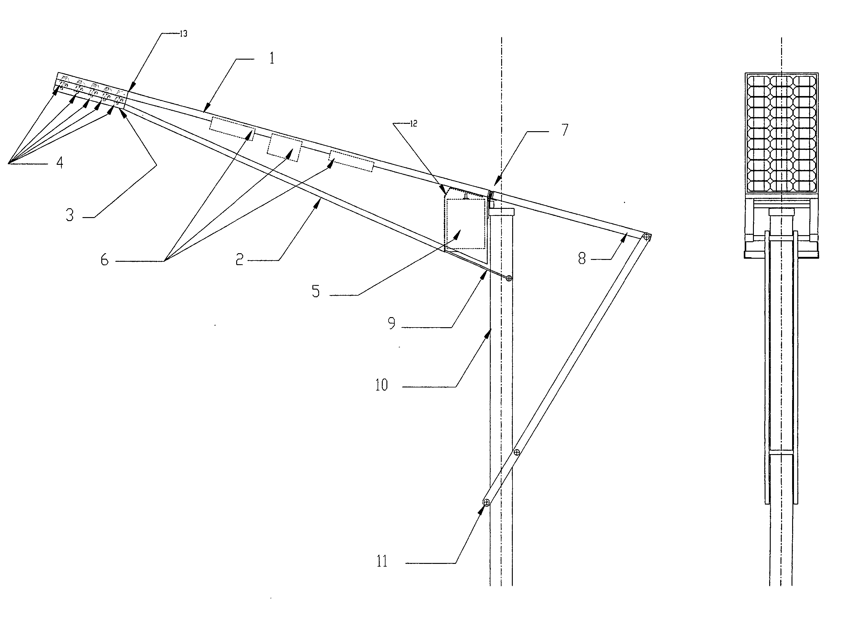
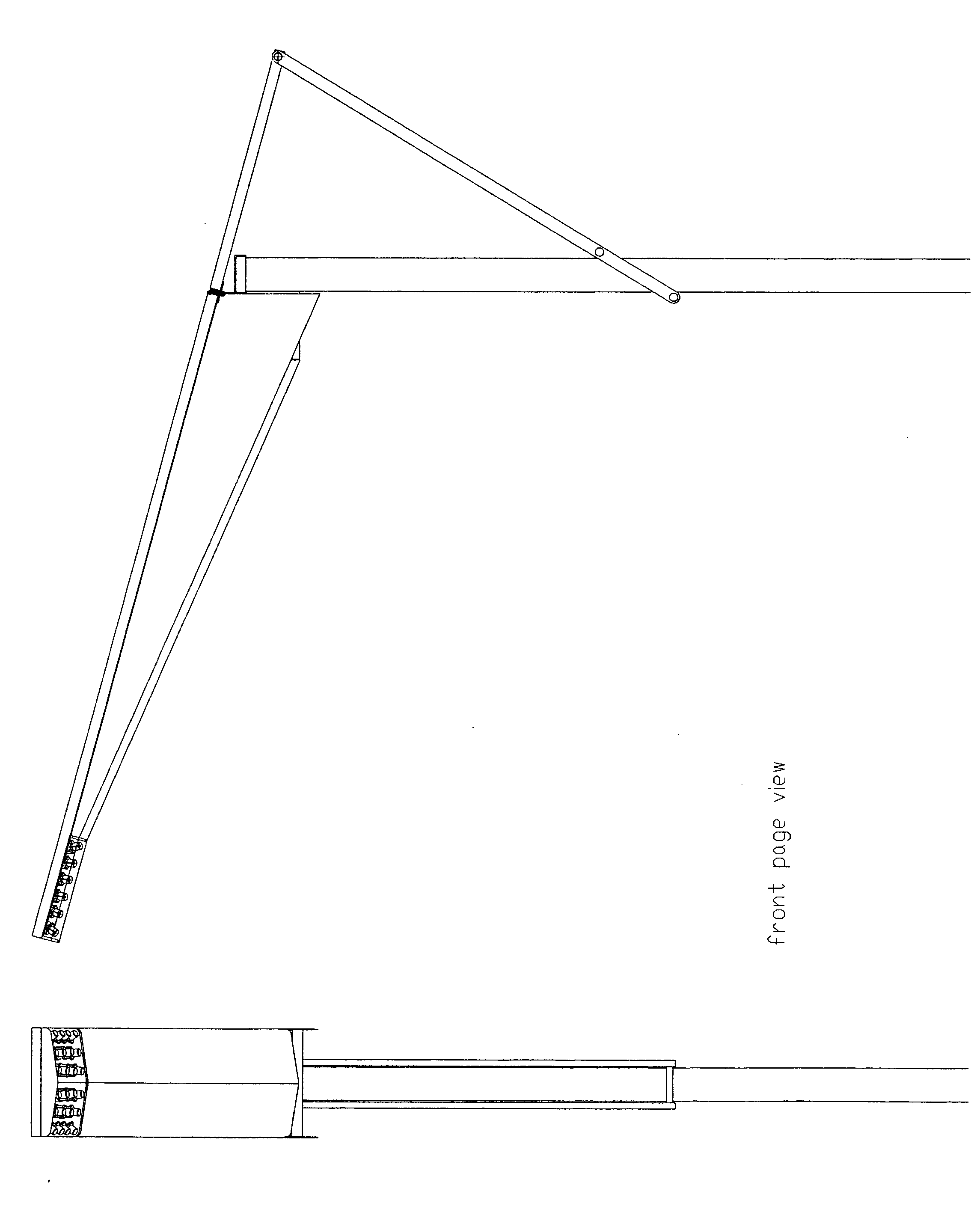
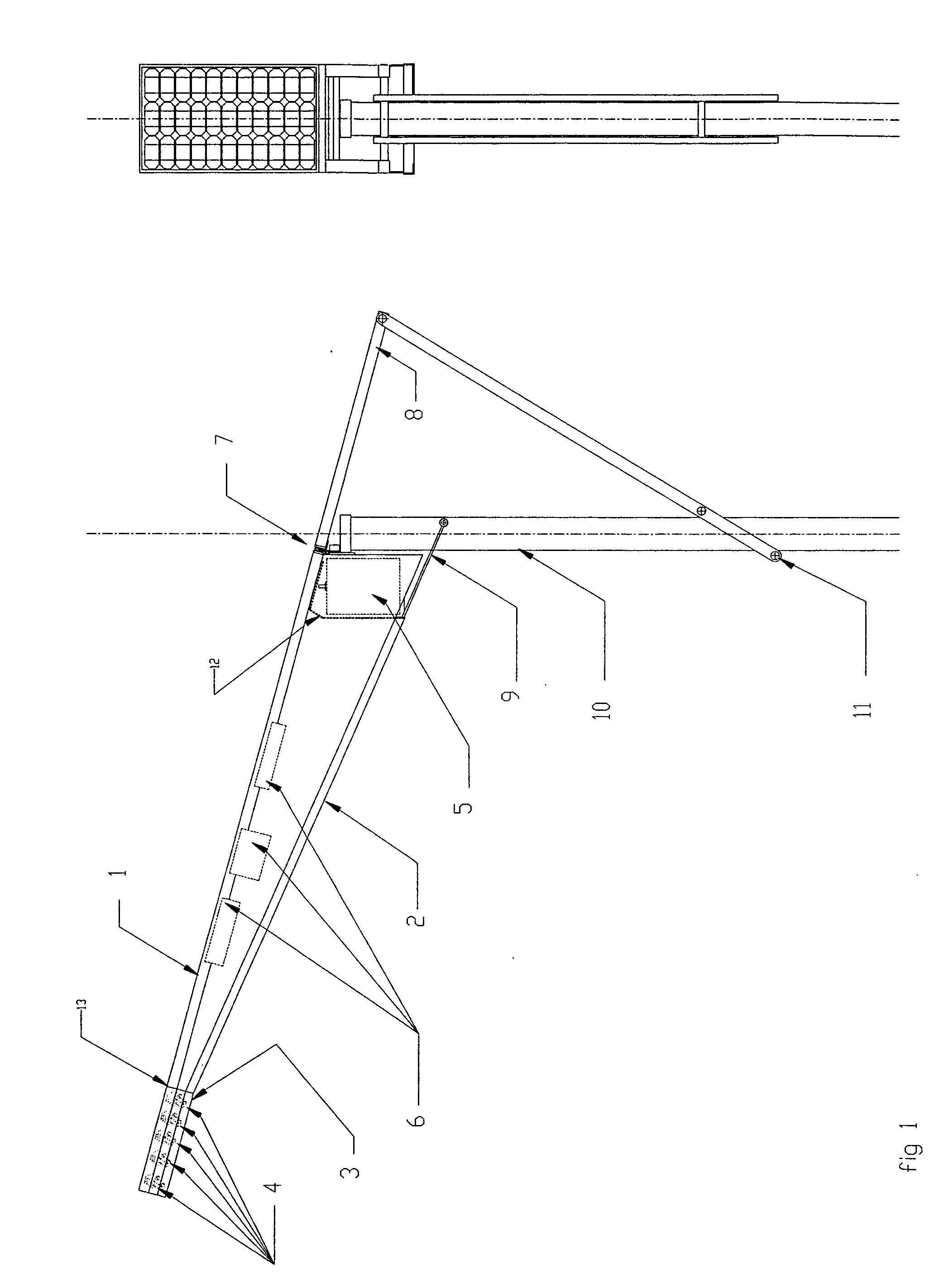
[0067]FIG. 1, FIG. 2 and FIG. 3 show a first embodiment of an outdoors luminaire attached to a square section street lighting mast 10.

[0068] The outdoors luminaire is comprised within an integral casing FIG. 1-2 and FIG. 2-1, this casing is integrated by the active element FIG. 2-1, in powering the luminaire and resolves several important aspects: as mechanical frame structure; as weather proof protective casing where wind, rain, snow, ultraviolet and infrared radiation and dust usually impairs the light performance of the luminaire itself; as temperature controlling dissipating element; and as an effective encasing for electronic circuitries involved as safety means against fire development and electric shock hazards.

[0069] The said active elements, which, comprises the luminaire encasing are:

[0070] The outer body FIG. 1-2 and FIG. 9-3, where the shape and geometry can be varied and is easily obtained by press forming or cast processes, made from a plurality of non corrosive fer...


PUM


Abstract

According to the present invention there is provided an outdoors self sufficient luminaire, weatherproof, characterized in that within the outer body are integrally housed: an array of solid state light emitting individually angle adjustable devices, a device for collecting and converting solar radiation into electrical energy, an electronic circuitry that administers the said generated electrical energy to replenish the power consumed from an accumulator during the absence of the said radiating source, an electronic circuitry that administer and control the levels of power necessary to excite individually the solid state light emitting devices in a programmable fashion, a structural integrated means for attaching the luminaire into a plurality of masts, and means for maintaining the temperature around the array of solid state light emitting devices within a predetermined range.

Description

CROSS-REFERENCE TO RELATED APPLICATIONS [0001] This non-provisional utility patent is submitted as the corresponding non provisional application for the Provisional patent application No. 60 / 506,314. filing date: Sep. 26, 2003 with confirmation No. 9628 which applicants are Juan Antonio Ertze Encinas and Jon Andoni Ertze Moguel with the title: Outdoors Self Sufficient Uninterruptable Luminare and is presented for filing purposes within the 12-month pendency period in accordance with 35 U.C.S. 119(e).STATEMENT REGARDING FEDERALLY SPONSORED RESEARCH OR DEVELOPMENT [0002] Not applicable REFERENCE TO SEQUENCE LISTING, A TABLE, OR A COMPUTER PROGRAM LISTING COMPACT DISK APPENDIX [0003] Not applicable BACKGROUND OF THE INVENTION [0004] 1. Field of the Invention [0005] The present invention relates to a self sufficient and uninterruptible, off the electrical grid, outdoors luminaire suitable for use to illuminate neighborhood streets, pathways and roadways, free and toll limited access hig...

Claims


Application Information

Patent Timeline
Patent Type & Authority Applications(United States)
IPC IPC(8): F21S9/03F21V14/02F21V21/30F21V23/04F21V29/00
CPCF21S2/005F21S9/037F21V14/02F21V21/30F21V23/0442F21V29/004F21V29/763F21W2131/103F21Y2101/02Y02B10/10F21V23/0457F21S8/085F21V29/75F21W2131/00F21Y2115/10Y02B20/72
Inventor ERTZE ENCINAS, JUAN ANTONIOERTZE MOGUEL, JON ANDONI
Owner ERTZE ENCINAS JUAN ANTONIO
Why Eureka
Try Eureka