One dimensional all-metal slab waveguide gas laser

a gas laser and allmetal slab technology, applied in gas laser construction details, laser details, electrical equipment, etc., can solve the problems of high manufacturing cost and relatively complex process of this kind of metal and ceramic sandwich structure, and achieve the effect of higher manufacturing cos

Active Publication Date: 2005-03-31
BEIJING BDHLASER SCI & TECH
View PDF1 Cites 6 Cited by
  • Summary
  • Abstract
  • Description
  • Claims
  • Application Information

AI Technical Summary

Benefits of technology

[0006] In order to overcome the problems that the prior slab waveguide laser structure is complex and higher manufacturing cost and a high order waveguide mode effect can

Problems solved by technology

The process of this kind of metal and ceramic sandwich str

Method used


Image

  • One dimensional all-metal slab waveguide gas laser
  • One dimensional all-metal slab waveguide gas laser
  • One dimensional all-metal slab waveguide gas laser

Examples


Embodiment Construction

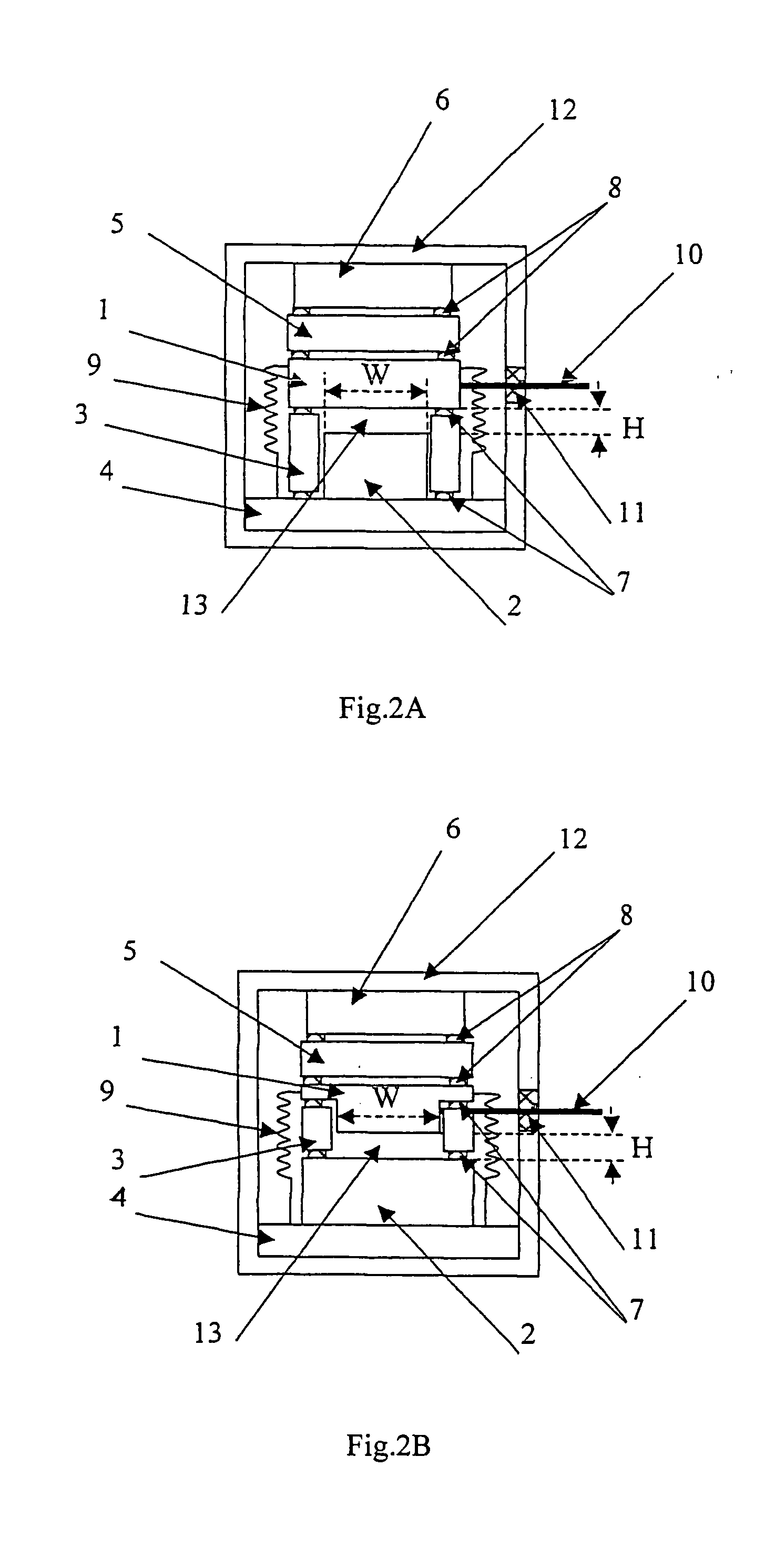
[0021] The one dimensional all-metal slab waveguide laser of the present invention has some kinds of structures shown in FIG. 2A, FIG. 2B, FIG. 2C, FIG. 3A, FIG. 3B and FIG. 3C. Metal top electrode 1, metal bottom electrode 2 and metal supporting block 3 compose a gas discharge region of the slab waveguide (height H=0.2-8 mm, width W=2-b 500 mm), i.e., a laser gain area. The metal bottom electrode 2 is disposed on metal bearing plate 4. There is no side wall of the rectangular space formed between metal top electrode 1 and metal bottom electrode 2, a one dimensional slab waveguide along a longitudinal direction of the electrodes is formed. In the waveguide, metal top electrode 1 and metal bottom electrode 2 have a guided-wave effect on an optical wave field perpendicular to the electrode direction, while in the direction parallel with metal top electrode 1 and metal bottom electrode 2, there is no guided-wave effect because there is no side wall boundary, and the optical wave field ...


PUM


Abstract

A one dimension all-metal slab waveguide gas laser comprises a slab waveguide gas discharge area and an optical resonator disposed in a metal vacuum chamber. The gas discharge area is formed by a top and a bottom metal electrodes and metal supporting blocks insolated with the electrodes. A metal liner plate and a metal press plate are sequentially disposed on upside of the metal electrodes. A metal supporting plate is disposed at underside of the metal electrodes. The metal top electrodes are connected with a supply power through link pins of the metal electrodes. An output mirror and a feedback mirror are respectively arranged at two sides of the optical resonator. An output window of the laser is disposed in the vacuum chamber. The present one dimension waveguide gas laser has advantages of good quality of high thermo conducting and simple processing as well as low cost, and can avoid appearing modulation of the output power of the laser which is caused by high order mode of the guide in current two dimension slab guide laser, thereby the quality of optical beam of the laser is improved.

Description

TECHNICAL FIELD [0001] The present invention relates to waveguide gas laser technology, in particular to a one dimensional all-metal slab waveguide gas laser. BACKGROUND ART [0002] The combination of RF transverse gas electric discharging technology with optical waveguide technology drives the rapid development of waveguide CO2 laser technology. In the past decade, RF transverse single waveguide CO2 laser technology has experienced a development process from all-ceramic waveguide structures to ceramics and metal sandwich waveguide structures to all-metal waveguide structures. In the all-ceramic waveguide structure (see FIG. 1A), a square waveguide is composed of two vacuum ceramic side walls 33 and two vacuum ceramic clamp plates 34, and disposed between two metal electrodes 32 connected with a high frequency power supply 31. A gain channel area is formed in the waveguide by discharge excitation. The advantage of the all-ceramic waveguide structure is low loss of optical wave. Along...

Claims


Application Information

Patent Timeline
IPC IPC(8): H01S3/00H01S3/03H01S3/0971H01S3/0975H01S3/223
CPCH01S3/0305H01S3/0315H01S3/2232H01S3/0975H01S3/0971
Inventor XIN, JIANGUOWU, JIANGXINGZHANG, ZHIYUANWANG, WEIPING
Owner BEIJING BDHLASER SCI & TECH
Why Eureka
Try Eureka