Housing for a fluid flow engine

a fluid flow and engine technology, applied in the direction of liquid fuel engines, positive displacement liquid engines, piston pumps, etc., can solve the problems of small tolerances and high cost, and achieve the effect of less cumbersom

Inactive Publication Date: 2005-03-31
BORGWARNER INC
View PDF6 Cites 72 Cited by
  • Summary
  • Abstract
  • Description
  • Claims
  • Application Information

AI Technical Summary

Benefits of technology

[0007] Of course, it is still more favorable if all three spaces, i.e. the two rotor spaces and the intermediate bearing space are surrounded by an integrally formed or cast housing.
[0008] A special advantage of the construction according to a preferred embodiment of the invention resides in that only a single technically high-grade part has to be produced instead of a plurality of them (involving an adaptation of tolerances to one another). The rotor spaces, open to the exterior, can be covered with a simple flange member so that mounting the housing requires only mounting the two flanges, thus being less cumbersome.

Problems solved by technology

These housing parts have then to be screwed or assembled in some way together, which is cumbersome, requires small tolerances and is, thus, expensive.

Method used


Image

  • Housing for a fluid flow engine
  • Housing for a fluid flow engine
  • Housing for a fluid flow engine

Examples


Embodiment Construction

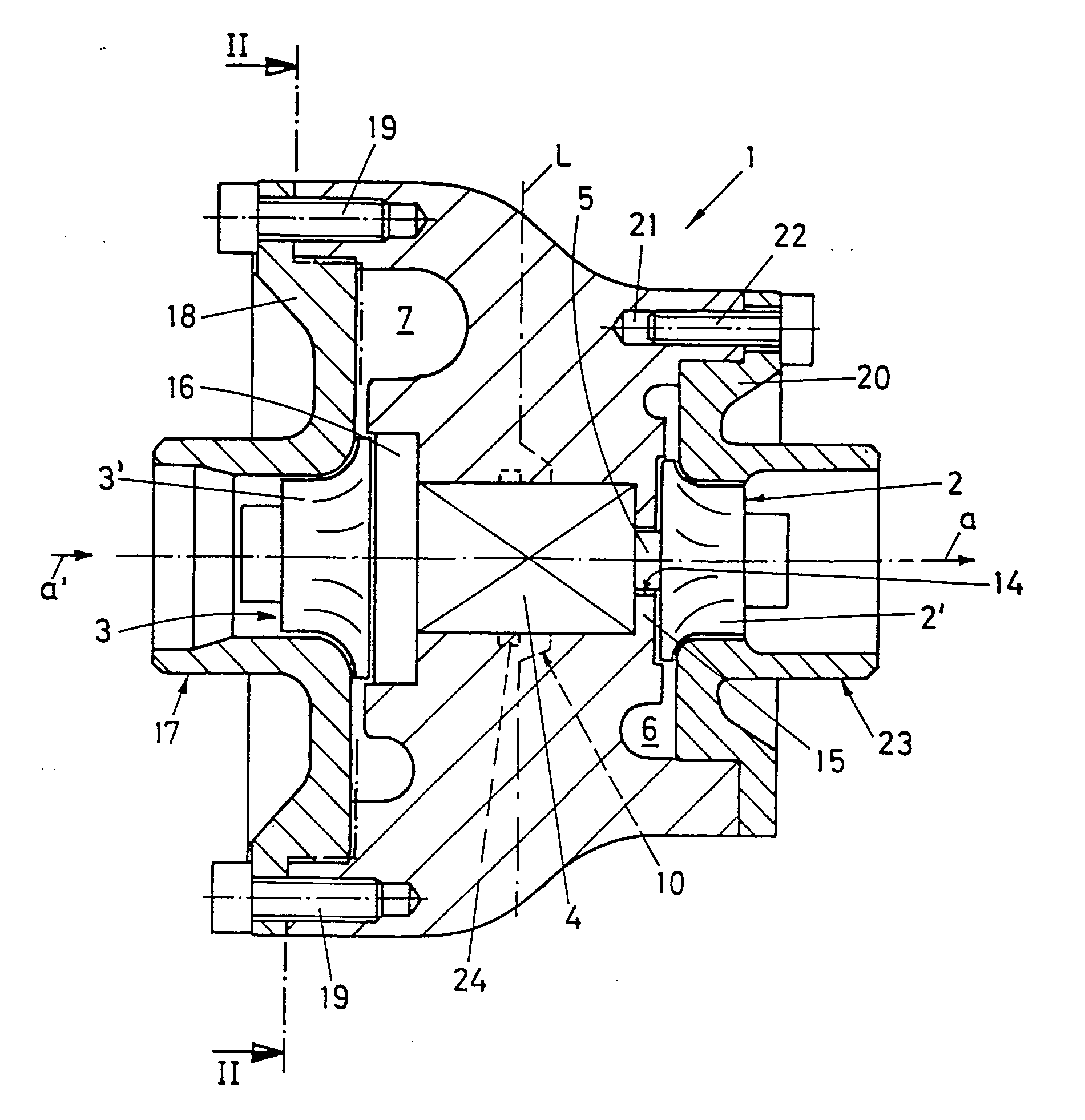
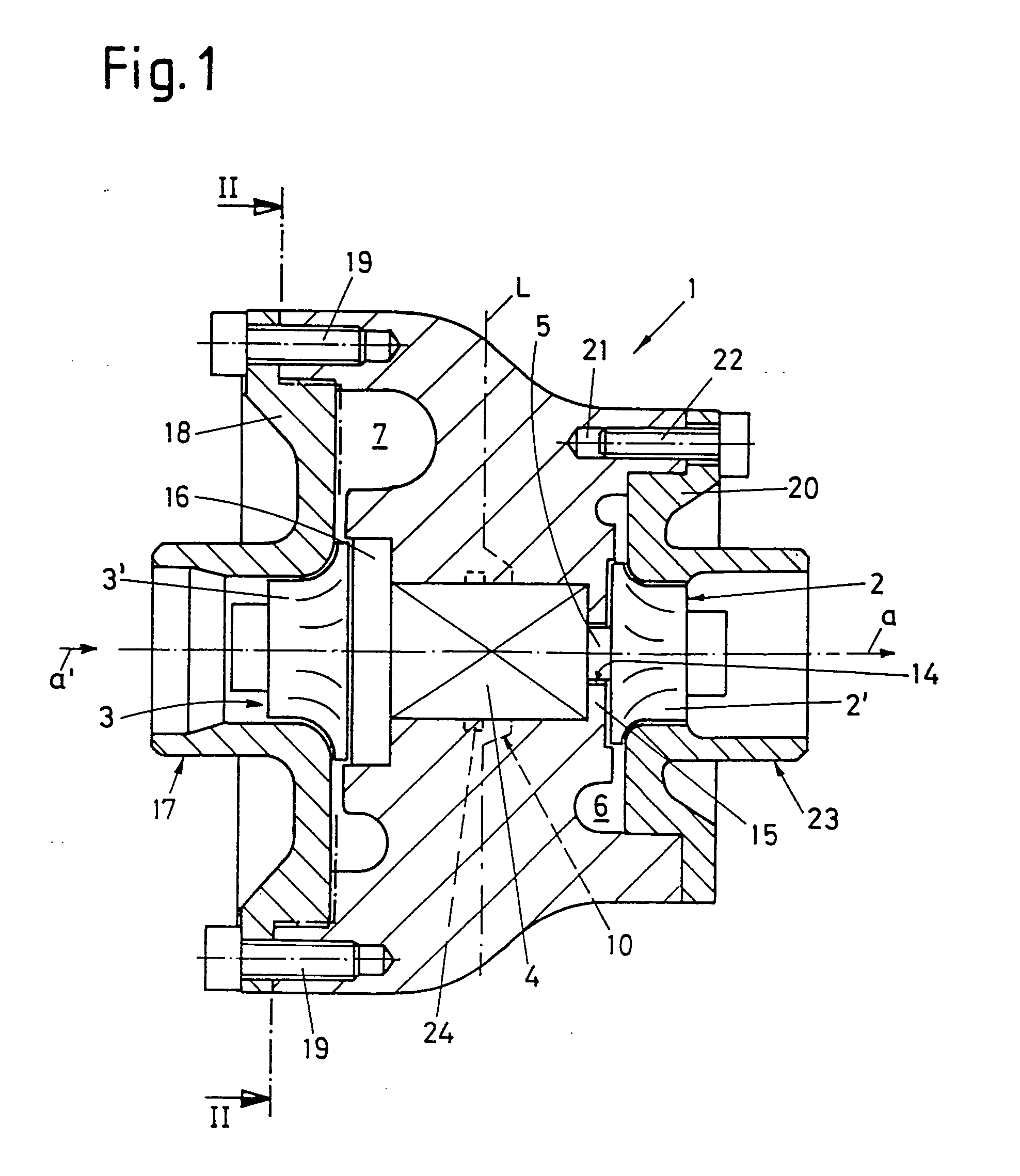
[0012] A single piece housing 1 which is, for example, produced from cast material, such as gray cast iron or a light metal casting, surrounds and defines with its inner walls a turbine rotor space 2 for a turbine rotor 2′, shown in FIG. 1, at one of its axial ends, a compressor rotor space 3 for a compressor rotor 3′ to be accommodated therein at the opposite axial end of the housing, and in-between a bearing space 4 for a shaft 5 which, as known to one of ordinary skill in the art, supports each of the two rotors 2′ and 3′ on one of its ends. To each of the rotor spaces 2, 3 a channel is assigned which, ordinarily, surrounds the rotor space in an approximately annular or spiral form, i.e. a supply channel 6 and a discharge channel 7.

[0013] A gaseous medium, i.e. in the case of a turbocharger an exhaust gas of a combustion motor, in the case of a secondary air charger it is air, or any other fluid, such as a liquid, is supplied to the supply channel 6 from a connection piece 8 sho...


PUM


Abstract

A housing (1) for a fluid flow engine comprises a first rotor space (2) for receiving and housing a turbine rotor, a bearing space (4) to house a shaft (5) of said turbine rotor, and a second rotor space (3) for receiving and housing a compressor rotor. The housing portions, which surround the bearing space (4), are integrally formed at least in part with those portions that surround at least one of the rotor spaces (2,3).

Description

FIELD OF THE INVENTION [0001] The present invention relates to a housing for a fluid flow engine, such as a turbocharger, a secondary air charger or the like. More particularly, the invention relates to a housing for such a fluid flow engine which comprises a first rotor space for receiving a turbine rotor, a bearing space for supporting a shaft supporting the turbine rotor at one of its ends, and a second rotor space for receiving and housing a compressor rotor, both rotor spaces being surrounded by channels for conveying a gas, such as exhaust gas or air. BACKGROUND OF THE INVENTION [0002] Such housings are known from a variety of documents, for example from document CA-1,270,120 or U.S. Pat. Nos. 2,860,827; 4,179,247 or 4,659,295. In all these known constructions, the housing consists of several housing parts, mostly three. For example, in most cases a separate housing part forms each the turbine rotor space, another one the bearing space and a third one the compressor rotor spac...

Claims


Application Information

Patent Timeline
Patent Type & Authority Applications(United States)
IPC IPC(8): F02B39/00F01D9/02F01D25/24F01D25/28F04D29/42
CPCF01D9/026F05D2220/40F01D25/24
Inventor ROEMUSS, CHRISTIANEDOEBEL, MANUELA
Owner BORGWARNER INC
Why Eureka
Try Eureka