Device for controlling liquid level position within condenser in rankine cycle apparatus

a technology of liquid level position and rankine cycle, which is applied in the direction of lighting and heating apparatus, machine/engine, separation process, etc., can solve the problems of affecting the durability of the pump unit, the liquid level position variation of the respective heat transmission area is minimized, and the control of the temperature of the condensed water based on the flow rate of the media to be cooled becomes very difficult, etc. problems, to achieve the effect of enhancing the control accuracy, reducing the variation of th

Inactive Publication Date: 2005-04-07
HONDA MOTOR CO LTD
View PDF9 Cites 36 Cited by
  • Summary
  • Abstract
  • Description
  • Claims
  • Application Information

AI Technical Summary

Benefits of technology

[0034] By contrast, the liquid-level-position control device of the present invention is arranged to reduce variation in the liquid level position of the condensed water within the condenser to minimize respective variation of the respective heat transmission areas of the gaseous-phase and liquid-phase portions in the condense

Problems solved by technology

Further, decrease in the pressure within the condenser 100 produces cavitations (bubbles) in the water supplying pump unit 110, which would result in functional deterioration of the pump unit 110 and adversely influence the durability of the pump unit 110.
Thus, if the portion occupied with the condensed water (105) increases or decreases due to variation (rise or fall) of the liquid level position 112, the surface area 117 of the heat transmission of the condensed water portion increases or decreases and so the temperature of the condensed water and the flow rate of the media to be cooled do not uniformly correspond to each other any longer, as a result of which control of the temperature of the condensed water based on adjustment of the flow rate of the media to be cooled would become very difficult.
Increase in the temperature of the condensed water in the condenser 100 produces cavitations (bubbles) in the water supplying pump unit 110, which would result in functional deterioration of the pump unit 110 and adversely

Method used


Image

  • Device for controlling liquid level position within condenser in rankine cycle apparatus
  • Device for controlling liquid level position within condenser in rankine cycle apparatus
  • Device for controlling liquid level position within condenser in rankine cycle apparatus

Examples


Embodiment Construction

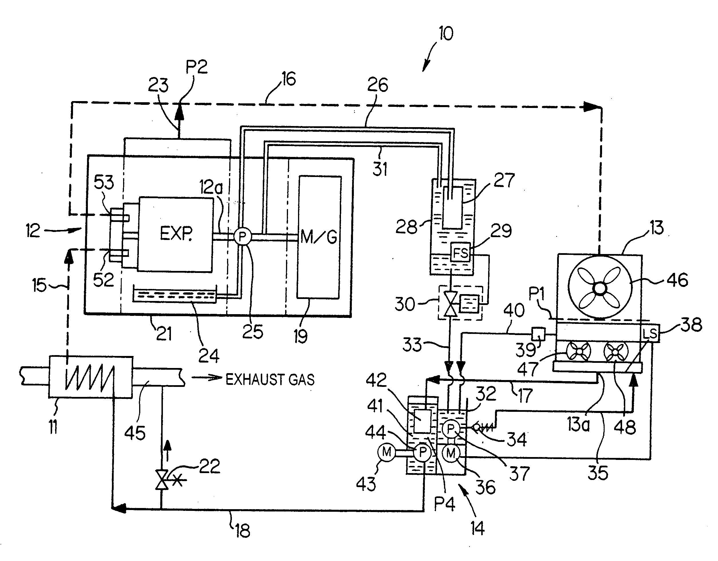
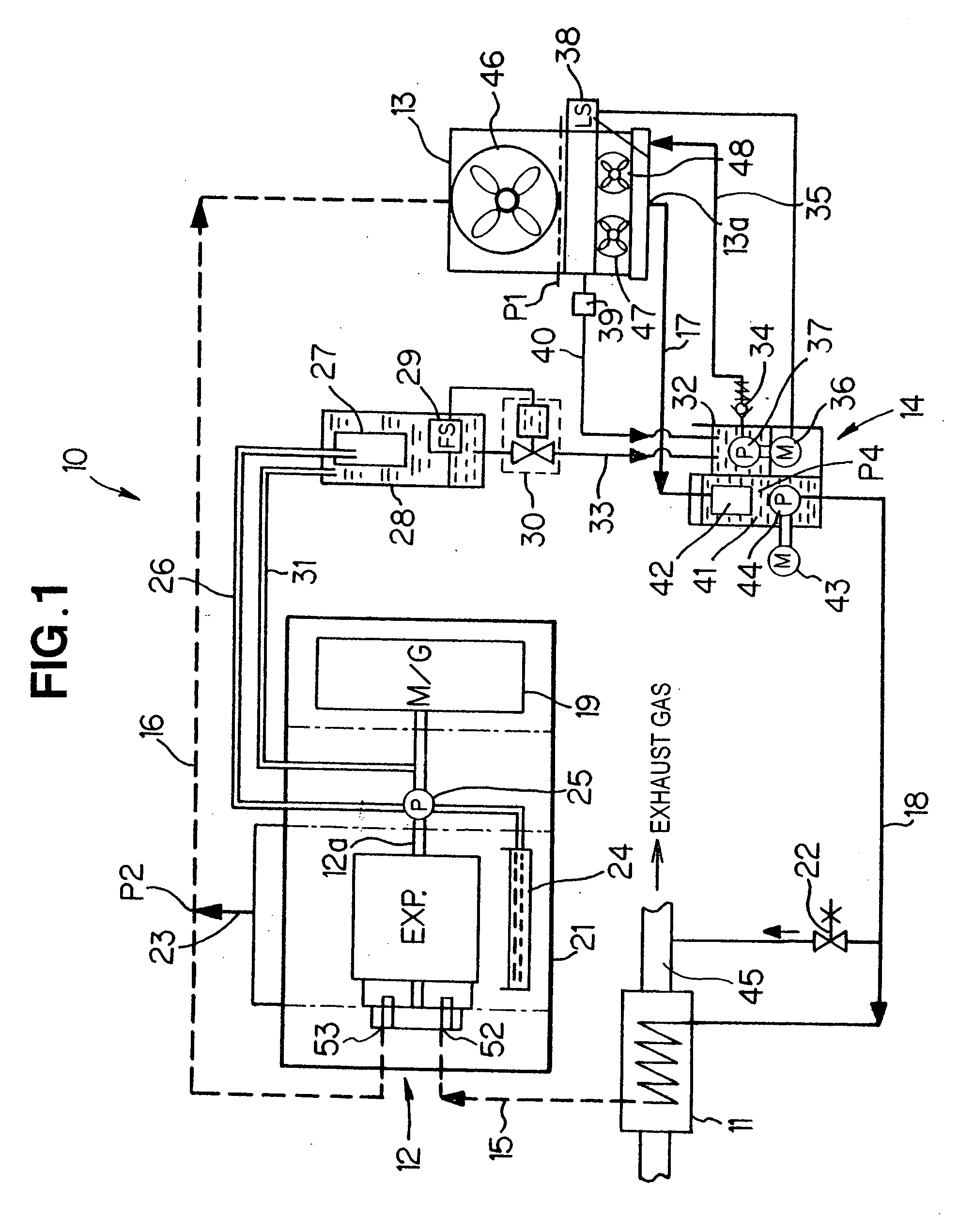
[0050] First, a description will be made about an example general setup of a Rankine cycle apparatus in accordance with an embodiment of the present invention, with reference to FIG. 1.

[0051] The Rankine cycle apparatus 10 includes an evaporator 11, an expander 12, a condenser 13, and a water supplying pump unit 14 provided with a supply pump.

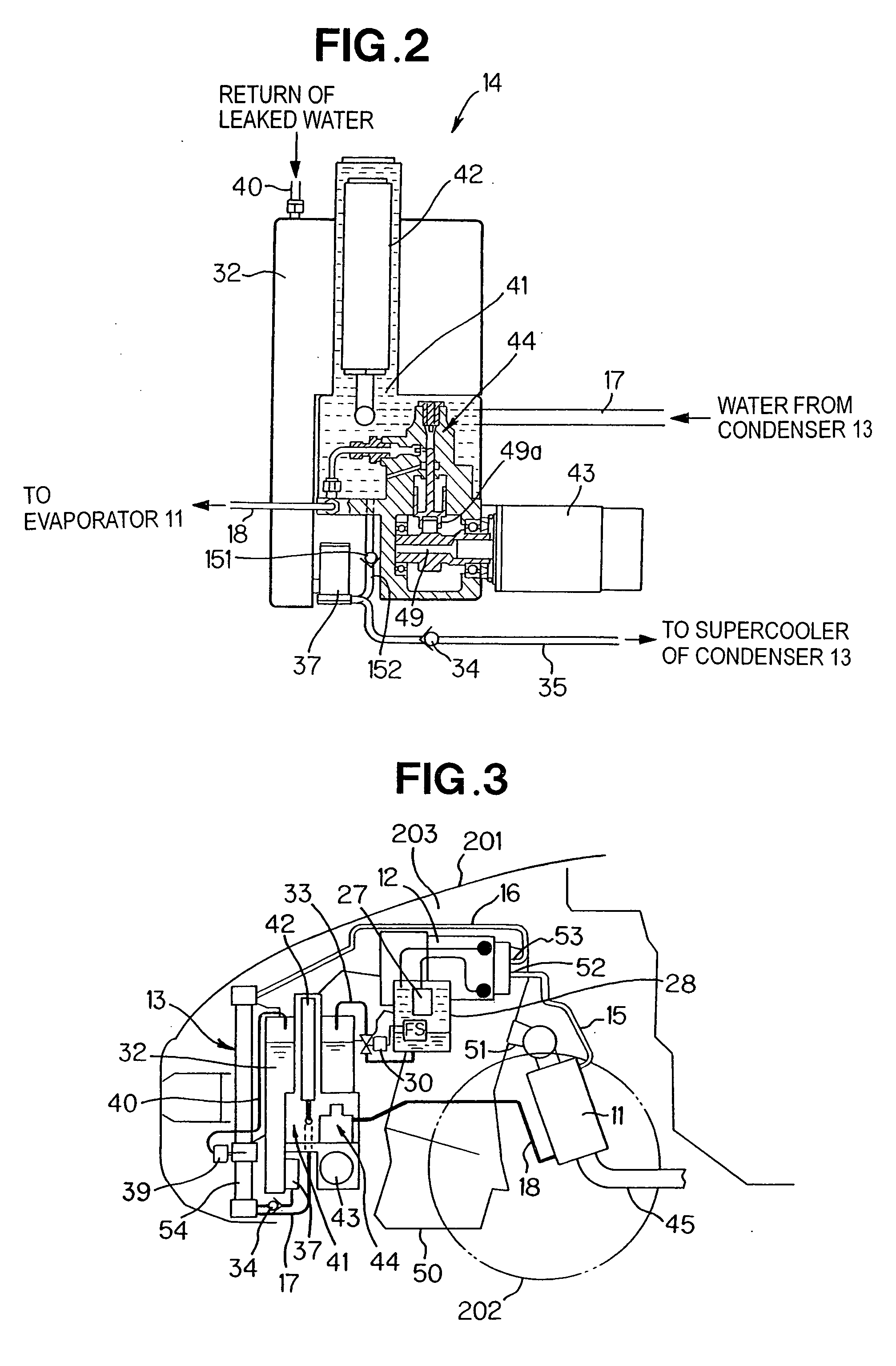
[0052] The evaporator 11 and the expander 12 are interconnected via a pipe 15, and the expander 12 and the condenser 13 are interconnected via a pipe 16. Further, the condenser 13 and the water supplying pump unit 14 are interconnected via a pipe 17, and the water supplying pump unit 14 and the evaporator 11 are interconnected via a pipe 18. With such a piping structure, there is formed closed circulation circuitry (circulation system) through which working media are circulated within the Rankine cycle apparatus 10 in the gaseous or liquid phase. The working media in the Rankine cycle apparatus 10 are water and water vapor.

[0053] The circula...


PUM

PropertyMeasurementUnit
Levelaaaaaaaaaa

Abstract

In a liquid-level-position control device for a condenser in a Rankine cycle apparatus, first and second reference liquid level positions are set. When a position of the fluid level is lower than the first reference liquid level position, water is replenished to a condenser by a liquid-phase working medium supply section. When the position of the fluid level is higher than the second reference liquid level position, the liquid-phase working medium is discharged from within the condenser by a liquid-phase working medium discharge section. In this way, the liquid level, which is a boundary surface between water vapor and condensed water within the condenser, can be constantly kept at an optimal position.

Description

FIELD OF THE INVENTION [0001] The present invention relates generally to devices for controlling liquid level positions within condensers in Rankine cycle apparatus, and more particularly to an improved liquid-level-position control device for a condenser in a Rankine cycle apparatus that is used, for example, as a vehicle-mounted apparatus for converting exhaust heat energy of a vehicle-mounted engine into mechanical energy. BACKGROUND OF THE INVENTION [0002] Rankine cycle apparatus have been known as systems for converting heat energy into mechanical work. The Rankine cycle apparatus include a structure for circulating water in the liquid and gaseous phases within a sealed piping system forming a circulation system in the apparatus. Generally, the Rankine cycle apparatus include a water supplying pump unit, an evaporator, an expander, a condenser, and pipes connecting between these components to provide circulation circuitry. [0003]FIG. 13 is a schematic block diagram of a general...

Claims


Application Information

Patent Timeline
IPC IPC(8): F02G5/02B01D5/00F01K9/00F01K23/06F03C99/00F16T1/10
CPCF01K9/00F16T1/10F01K23/065
Inventor TANIGUCHI, HIROYOSHIUDA, MAKOTO
Owner HONDA MOTOR CO LTD
Why Eureka
Try Eureka