Image pick-up device and image pick-up system using the image pick-up device

Inactive Publication Date: 2005-04-07
CANON KK
View PDF2 Cites 31 Cited by
  • Summary
  • Abstract
  • Description
  • Claims
  • Application Information

AI Technical Summary

Benefits of technology

[0016] According to the present invention, the potential well structure equipped by the image pick-up device is arranged not only on the light-receiving portion but also in the area in which the poly-silicon wiring and the light-receiving portion overlap each other. Thereby the opened are

Problems solved by technology

It is confirmed as to the image pick-up element using the potential well structure that, when the frontage thereof is too small, it is impossible to take in sufficient incident light, and that the light collection efficiency thereof scarcely differs from tha

Method used


Image

  • Image pick-up device and image pick-up system using the image pick-up device
  • Image pick-up device and image pick-up system using the image pick-up device
  • Image pick-up device and image pick-up system using the image pick-up device

Examples


first embodiment

[0032] (First Embodiment)

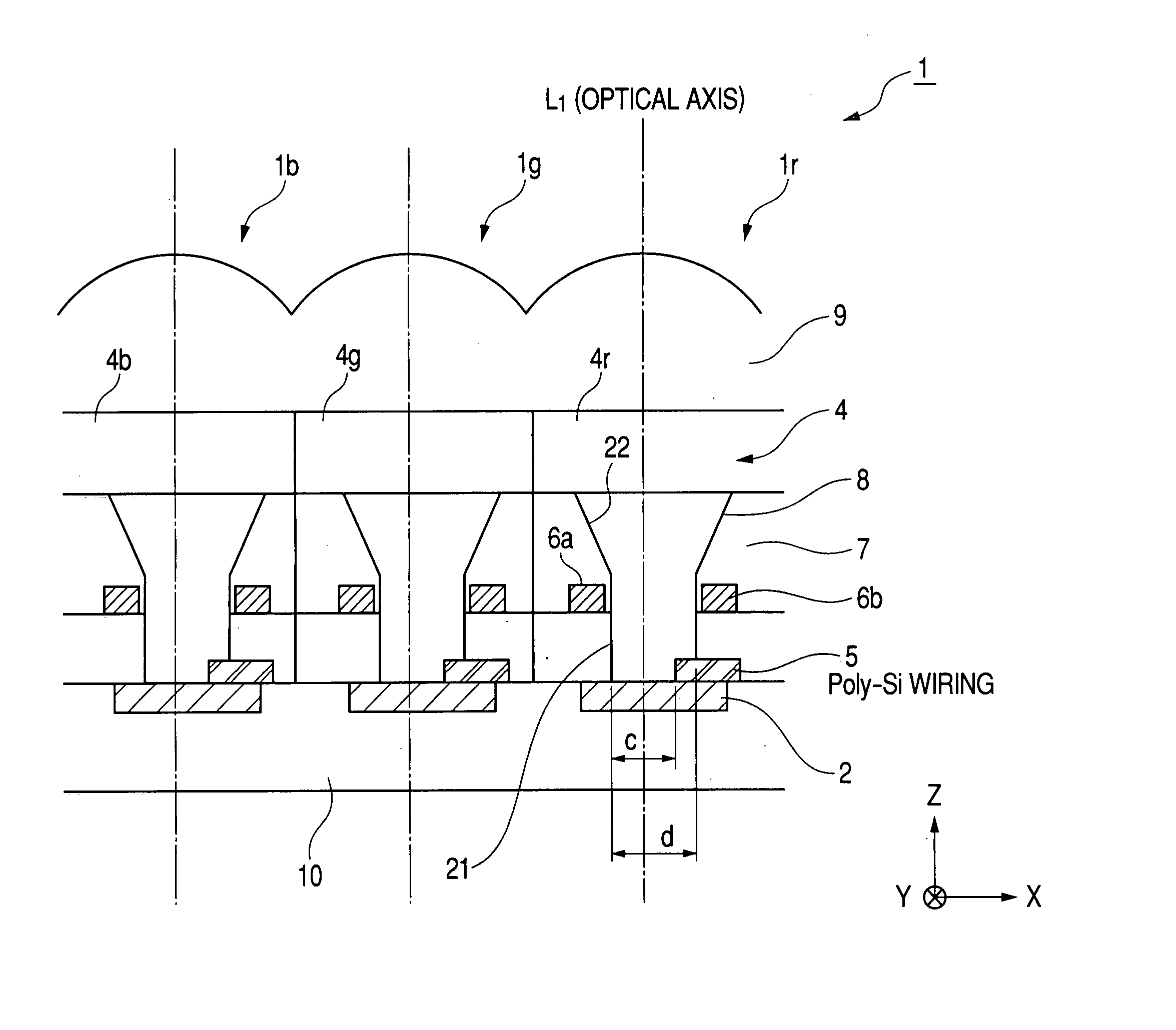
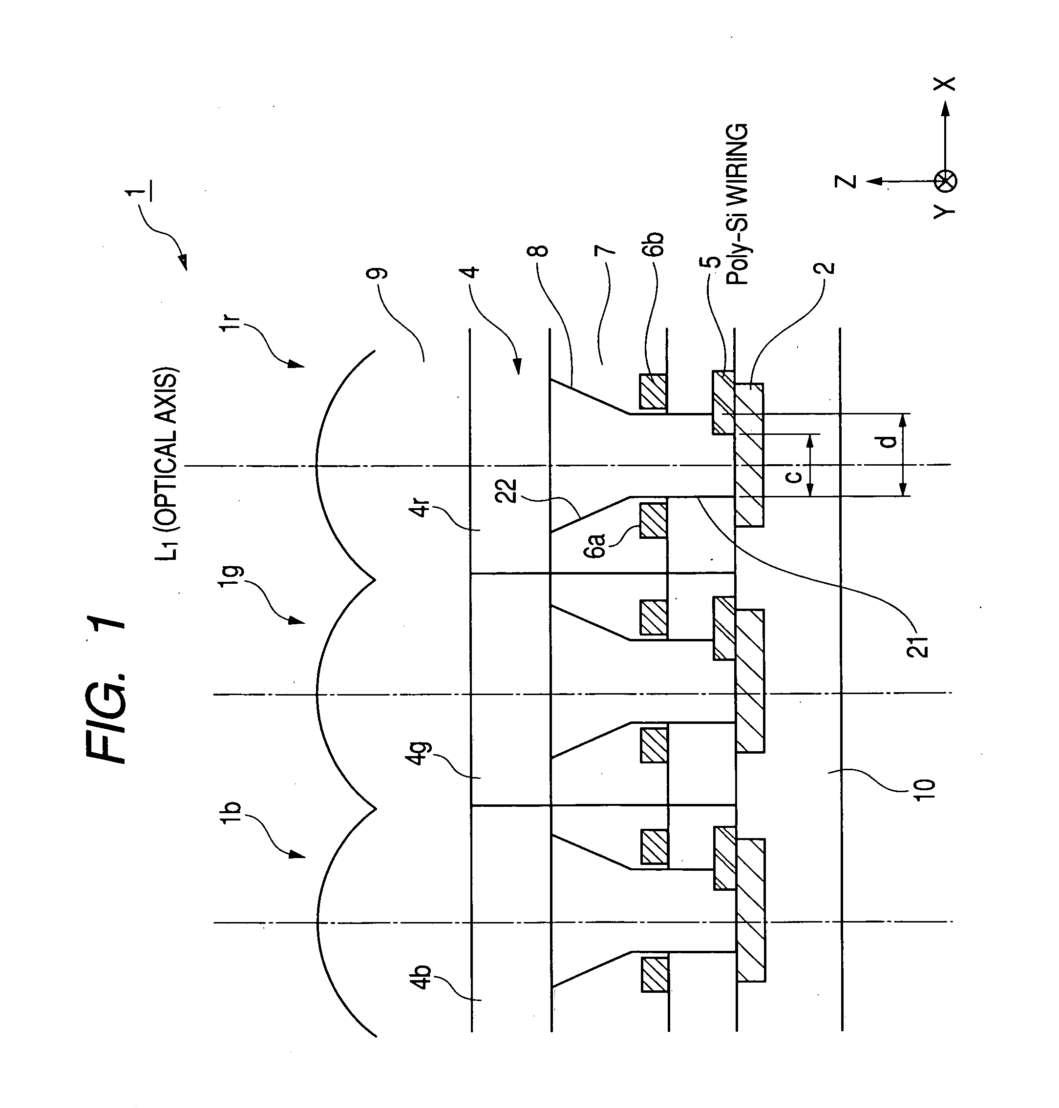
[0033]FIG. 1 shows a sectional view of an image pick-up device 1 according to a first embodiment of the present invention. The image pick-up device 1 includes a wavelength selection layer 4 common to each image pick-up element 1r, 1g and 1b as a color filter. Wave selection portions 4r, 4g and 4b are formed in areas of the wavelength selection layer 4 corresponding to the respective image pick-up elements 1r, 1g and 1b. Thus, the image pick-up device 1 is configured in order that each of the image pick-up elements 1r, 1g and 1b can receive read light, green light and blue light, respectively. The image pick-up device 1 is used as, for example, an area sensor of a still video camera. Incidentally, any of the image pick-up elements 1r, 1g and 1b has the same figure, and accordingly the image pick-up element 1r will be described as a representative in the following.

[0034] The image pick-up element 1r includes the wavelength selection layer 4 (the wavelength se...

second embodiment

[0042] (Second Embodiment)

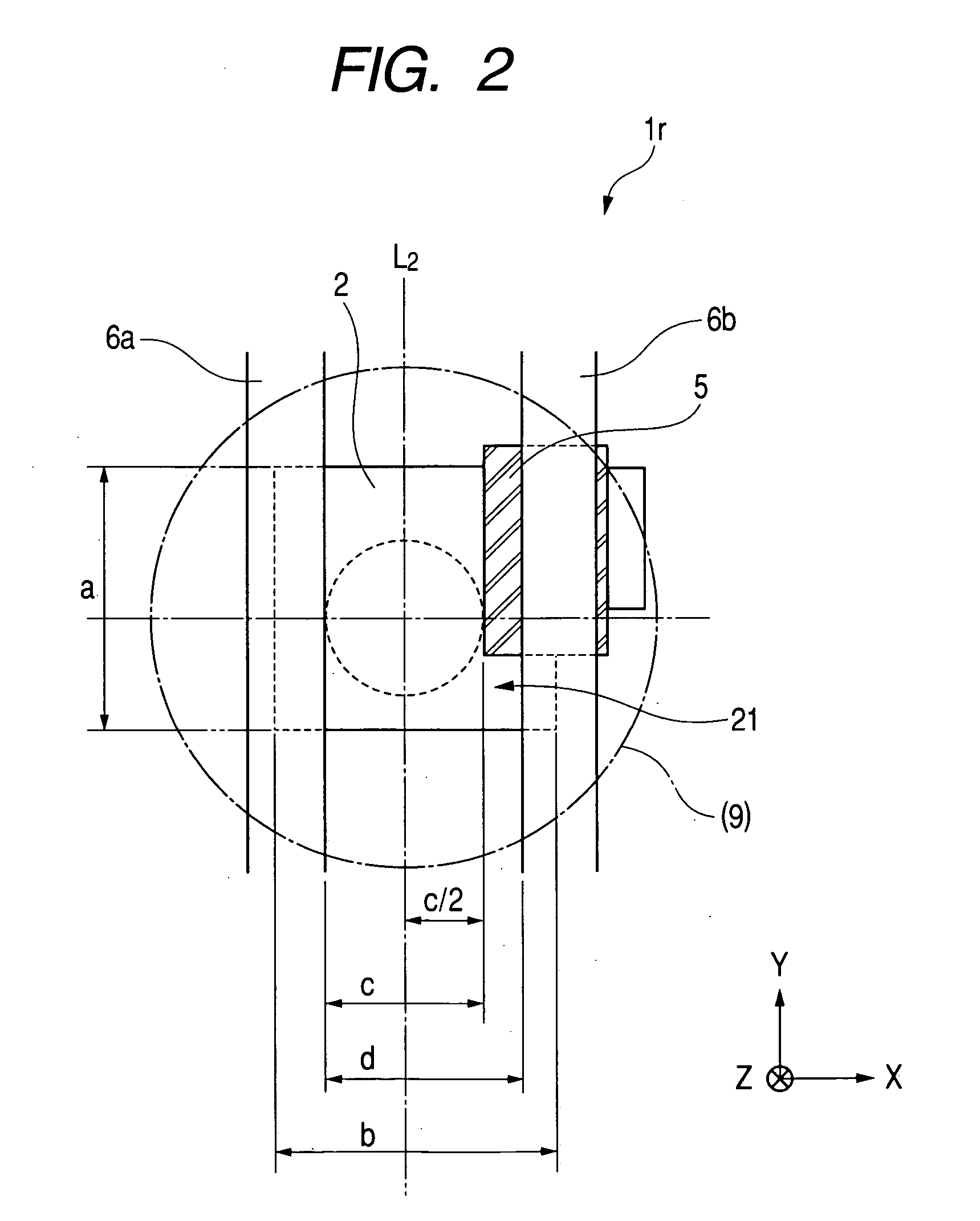
[0043] The image pick-up device 1 of the first embodiment is configured so that the optical axis (the center line L1) of the microlens 9 is positioned at the center between the poly-silicon wiring 5 and the inner wall of the potential well structure 21 on the side on which the poly-silicon wiring 5 is not formed as a result. However, the arrangement of the microlens is not limited to that one, and the characteristics of an image pick-up element can be changed by changing the arrangement of the microlens to the potential well structure.

[0044]FIG. 3 shows an example of the image pick-up element according to a second embodiment. FIG. 4 is a top view for illustrating the positional relations among each piece of wiring of the image pick-up element of FIG. 3. An image pick-up element 11r shown in FIGS. 3 and 4 is the same in the structural portions other than a microlens 19 as those of the image pick-up element 1r of FIGS. 1 and 2. The same structural portions a...

third embodiment

[0051] (Third Embodiment)

[0052]FIG. 8 is a block diagram of an embodiment of an image pick-up system using an image pick-up device according to the embodiments of the present invention described above.

[0053] An image pick-up system 40 shown in FIG. 8 is an image pick-up system such as a still video camera. When the image pick-up system 40 is roughly divided, the image pick-up system 40 is composed of an optical section 40a for forming an image, a processing section 40b for performing the photoelectric conversion of the formed image and for processing the signal obtained by the photoelectric conversion, a recording section 40c for performing the recording and the like of the data worked and processed by the processing section 40b, and a control section 40d for controlling the drive of each section.

[0054] The optical section 40a is composed of a lens 42 for forming an optical image of a subject image on an image surface, a barrier 41 used as a protection of the lens 42 and also used...


PUM


Abstract

With an aim of receiving a subject image at good sensitivity by improving the light collection efficiency of incident light, an image pick-up element includes a light-receiving portion, poly-silicon wiring formed on the light-receiving portion, and a potential well structure. The poly-silicon wiring is arranged so as to be overlapped with at least a part of the light-receiving portion, and is electrically connected to the light-receiving portion to perform the control of electric charges generated at the light-receiving portion, the switching of the light-receiving portion, and the like. The potential well structure is formed in at least a part of the area of the light-receiving portion in which the poly-silicon wiring is arranged, and the opened area of the potential well structure is sufficiently secured. The incident light entering the potential well structure is totally reflected by the inner wall of the potential well structure, and reaches the light-receiving portion or the poly-silicon wiring. The incident light reaching the poly-silicon wiring is transmitted through the poly-silicon wiring to be received by the light-receiving portion.

Description

BACKGROUND OF THE INVENTION [0001] 1. Field of the Invention [0002] The present invention relates to an image pick-up device and an image pick-up system for picking up a subject image, and more particularly to an image pick-up element having poly-silicon wiring arranged on a light-receiving portion thereof. [0003] 2. Description of Related Art [0004] As a conventional image pick-up element for introducing incident light into a light-receiving portion efficiently for performing a photoelectric conversion, for example, as disclosed in Japanese Patent Application Laid-Open No. H8-321595, a structure including an inter-layer lens in addition to a microlens as shown in FIG. 11 has been proposed. An image pick-up element 101 of FIG. 11 includes a light-receiving portion 102 formed in a silicon wafer 110, a microlens 109 for collecting incident light, a high refractive index portion 108, which is provided at a lower layer of the microlens 109 and has a refractive index higher than that of ...

Claims


Application Information

Patent Timeline
IPC IPC(8): H01L27/00H01L31/0232H01L27/14H04N5/335H04N5/369
CPCH01L27/14627H01L27/14625
Inventor DOBASHI, HIDEKI
Owner CANON KK
Why Eureka
Try Eureka