
Methods and apparatus for self-optimization of electrospray ionization devices

a technology of electrospray ionization and self-optimization, which is applied in the direction of particle separator tube details, dispersed particle separation, separation processes, etc., can solve the problems of requiring significant time, effort and manual effort, and the optimization process is often a repetitive and time-consuming procedure, and the electrospray optimization step alone requires a significant amount of time, effort and expertise. , to achieve the effect of effective interfa

Inactive Publication Date: 2005-04-07
NORVIEL VERN
View PDF38 Cites 54 Cited by
  • Summary
  • Abstract
  • Description
  • Claims
  • Application Information

AI Technical Summary

Benefits of technology

[0005] The invention provides methods and apparatus related to microfluidic chips and electrospray ionization applications. Various aspects of the invention can be appreciated individually or collectively to provide an effective interface for microfluidic sy

Problems solved by technology

Electrospray ionization mass spectrometry requires extensive optimization of electrospray interface conditions and this optimization process presents a significant challenge.
The optimization process is often a repetitive and time-consuming procedure requiring significant time, expertise, and manual effort.
Accordingly, a significant amount of time, effort and expertise are needed for the electrospray optimization step alone.

Method used


Image

  • Methods and apparatus for self-optimization of electrospray ionization devices
  • Methods and apparatus for self-optimization of electrospray ionization devices
  • Methods and apparatus for self-optimization of electrospray ionization devices

Examples


Embodiment Construction

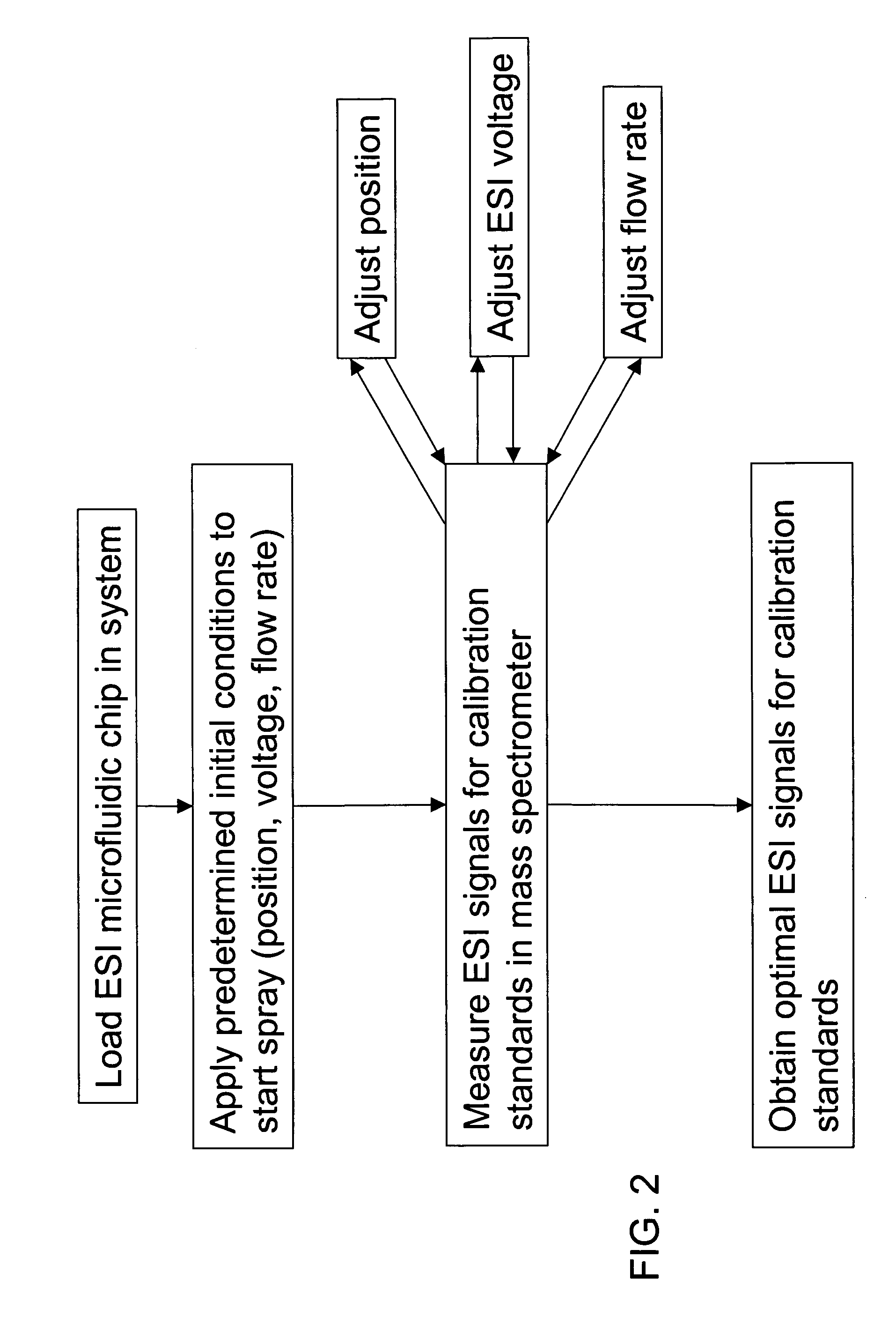
[0018] The invention provides self-optimized electrospray ionization devices and related methodologies. What may be defined as optimal spray conditions includes one or more preferred sets of inter-related measurements or characteristics that can be observed during mass spectrometric analysis such as a high, stable electrospray current and signal for a particular analyte. Optimal spray conditions can be also characterized with the formation of a stable Taylor cone and minimal or reduced background signal from a selected solvent that is used with the analyte. Methods and apparatus are provided in accordance with the invention to optimize electrospray conditions based on detecting and measuring predetermined electrospray ionization parameters associated with a particular solution undergoing mass analysis.

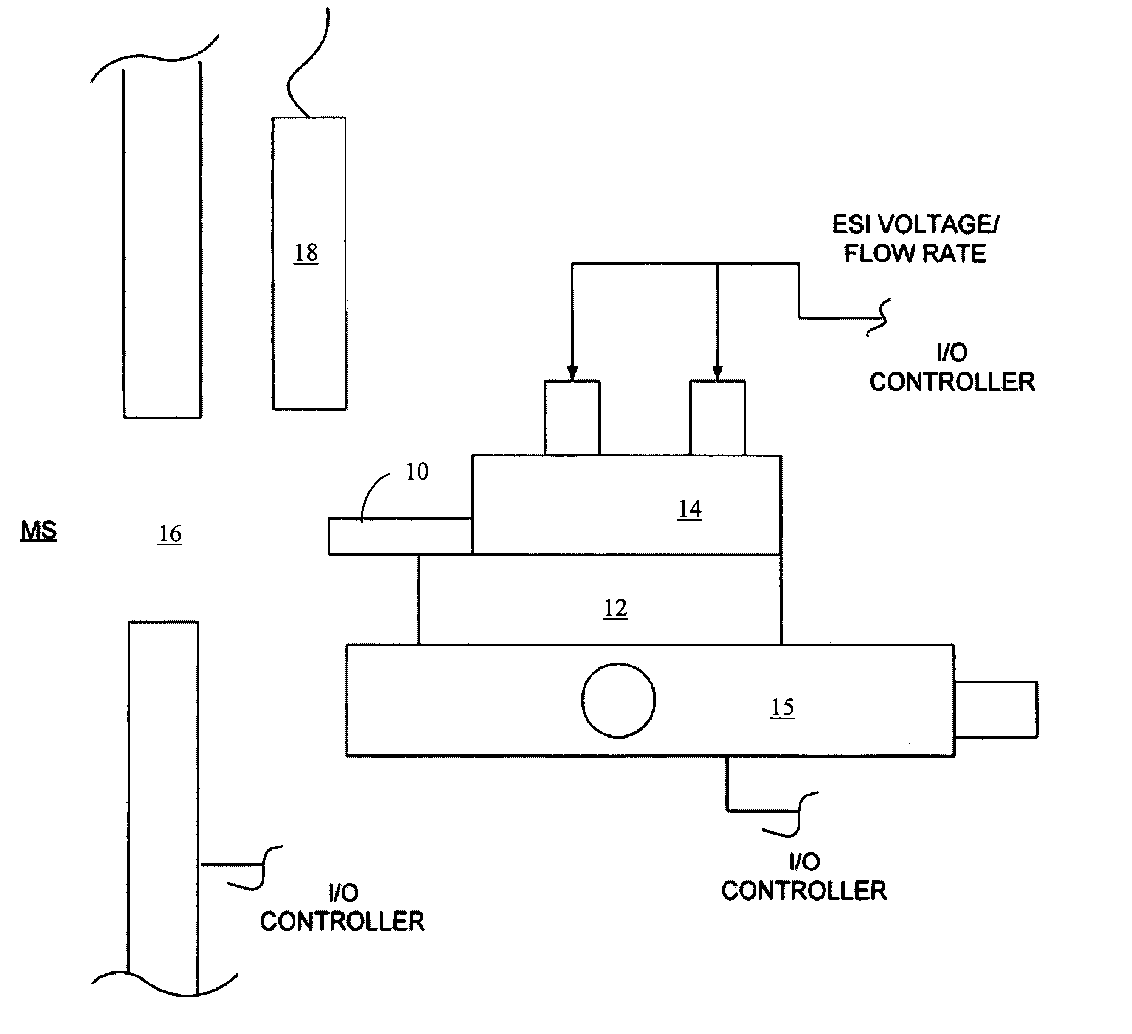
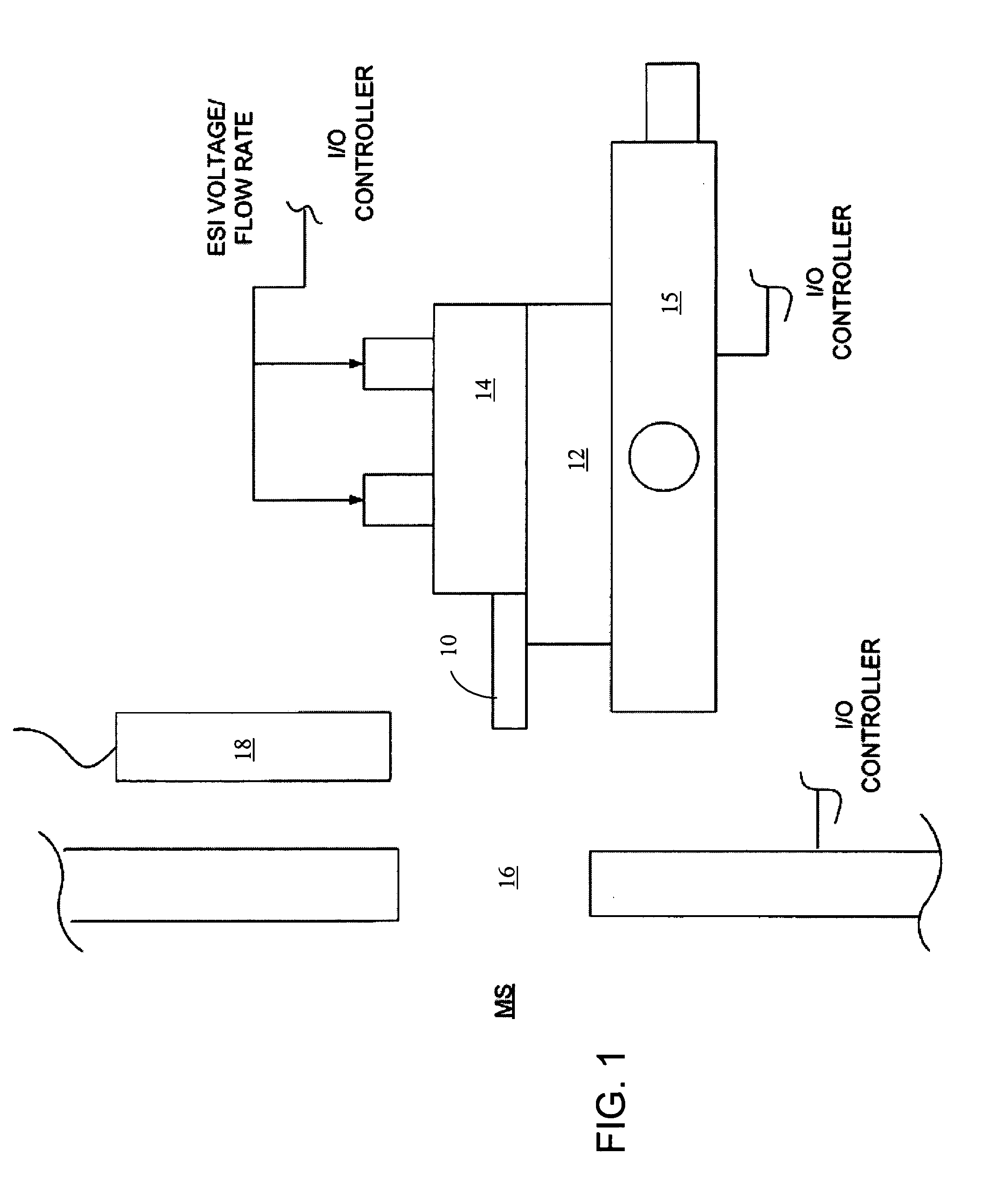
[0019] As shown, in FIG. 1, the invention may be applied to a variety of electrospray ionization (ESI) mass spectrometer interfaces to achieve optimization. A microfluidic chip or oth...


PUM


Abstract

An automated electrospray ionization (ESI) device and related methods to optimize electrospray interface conditions for mass spectrometric analysis. The optimization process can be performed with calibration or optimization solutions that produce expected ESI parameters such as an ESI signal or an ion current. The ESI device may include an input / output (I / O) controller that is coupled to an electrospray assembly including an XYZ stage for positioning an electrospray emitter relative to a mass spectrometer orifice. The I / O controller may be connected to a power supply for applying an adjustable electrospray ionization voltage, and an adjustable flow regulator that alters the flow of solution by modifying applied voltage and / or pressure. A central processing unit instructs the I / O controller to control selectively the electrospray assembly based on the resultant signals from the mass spectrometer or the ion currents within the mass spectrometer in accordance with a predetermined optimization algorithm. The resulting ESI signal or ion currents are monitored and provide feedback to the I / O controller which can automatically instruct selected system components to make adjustments as needed to attain optimal settings that produce expected ESI signals or ion currents in the mass spectrometer for selected solutions.

Description

FIELD OF THE INVENTION [0001] The invention relates to electrospray ionization mass spectrometry. More particularly, the invention relates to self-optimization apparatus and improved methods for performing electrospray ionization for mass spectrometric analysis. BACKGROUND OF THE INVENTION [0002] Electrospray ionization mass spectrometry requires extensive optimization of electrospray interface conditions and this optimization process presents a significant challenge. Whenever a variable or component of the electrospray interface is changed, a variety of adjustments is consequently required thereafter. For example, an electrospray ion source may be interfaced to a mass spectrometer to deliver solution ions into the mass spectrometer orifice or capillary entrance. The ions created by the source are then swept into the mass spectrometer for analysis. During the course of experimentation, it is often necessary however to change and physically reposition system components, for example, ...

Claims


Application Information

Patent Timeline
IPC IPC(8): H01J49/04
CPCH01J49/167H01J49/0018
Inventor STULTS, JOHN T.HELLER, JONATHAN C.
Owner NORVIEL VERN
Learn More