Indicator system having multiple leds

a technology of indicator system and led, which is applied in the direction of identification means, instruments, lighting support devices, etc., can solve the problem that the effect of less likely to be achieved in the control of the flashing switch

Inactive Publication Date: 2005-04-07
ANDEN CORP +1
View PDF8 Cites 29 Cited by
  • Summary
  • Abstract
  • Description
  • Claims
  • Application Information

AI Technical Summary

Benefits of technology

Since the signal indicating an open-circuit is not transmitted to the flashing control circuit if the source voltage is lower than a predetermined level, improper control of the flashing switch is less likely to b

Problems solved by technology

Since the signal indicating an open-circuit is not transmitted to the flashing control circuit if the source vol

Method used


Image

  • Indicator system having multiple leds
  • Indicator system having multiple leds
  • Indicator system having multiple leds

Examples


first embodiment

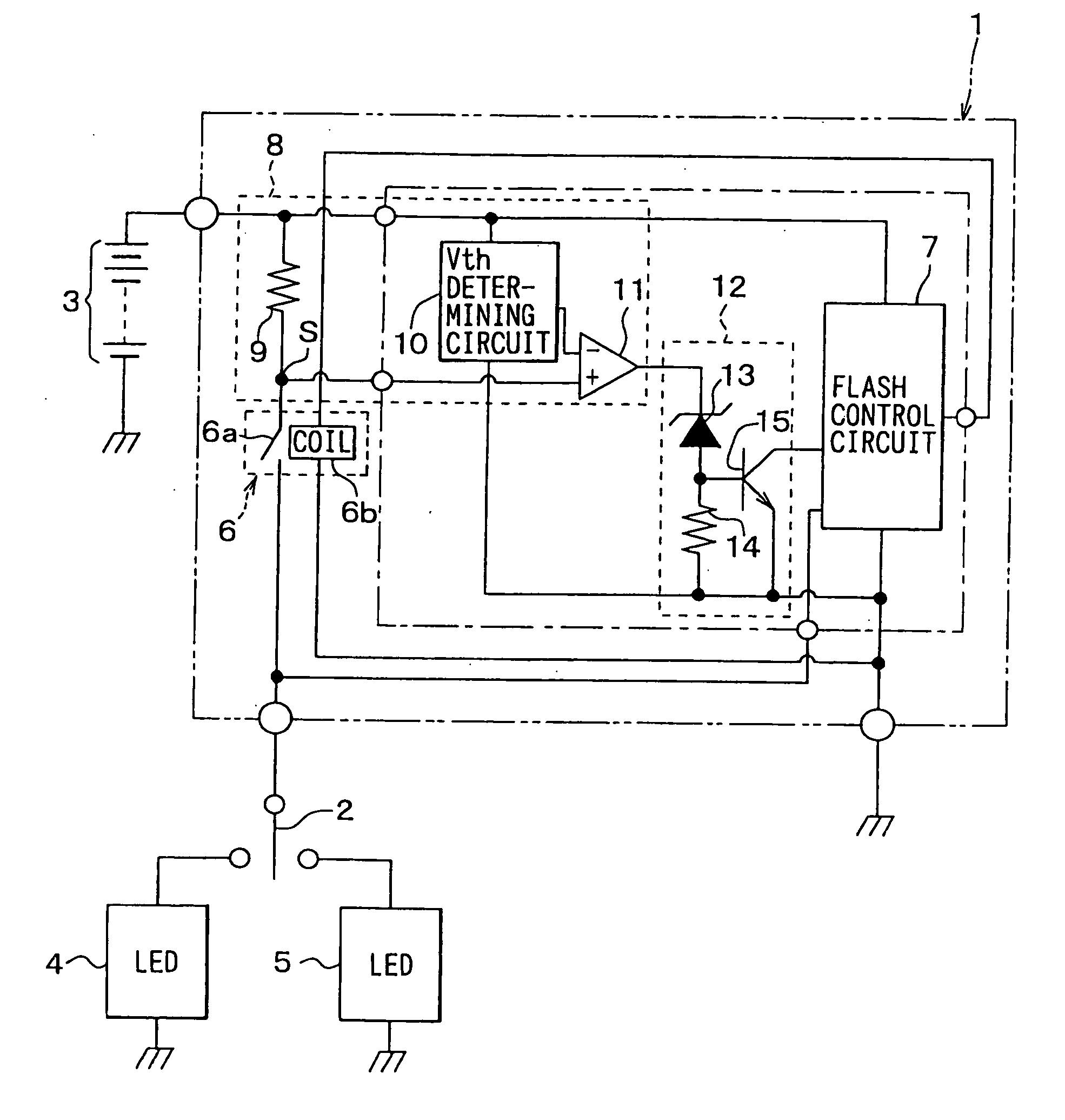
Referring to FIG. 1, an indicator system includes an indicator control unit 1, an indicator switch 2, a battery 3, a left LED indicator 4, and a right LED indicator 5. The indicator control unit 1 controls illumination of the left indicator 4 and the right indicator 5. It turns on the left indicator 4 or the right indicator 5, whichever selected by a driver through operation of the indicator switch 2 and supplied with power from the battery 3. The indicator switch 2 is arranged behind a steering wheel inside a vehicle.

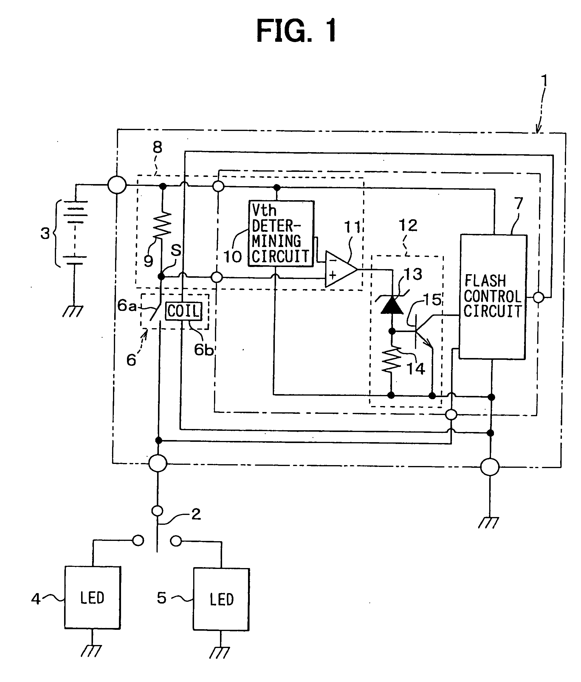
Each indicator 4, 5 is constructed of multiple LEDs 110 and resistors as shown in FIG. 2. An n number of LEDs 110 and a resistor 111 are connected in series. This series circuit is referred to as an LED line. An m number of LED lines are connected in parallel with each other. The indicator 4, 5 flashes when power is supplied from the battery 3 to each LED line via the indicator control unit 1 and the indicator switch 2. Although only one for each Indicator 4, 5 is s...

second embodiment

Referring to FIG. 5, an indicator control unit 20 has a similar configuration to that of the first embodiment. The low-voltage filtering circuit 12 is not included in this indicator control unit 20. Moreover, a threshold voltage determining circuit 21 is included instead of the threshold voltage determining circuit 10. Other components and circuits are the same as those in the first embodiment. Therefore, they will not be discussed in this second embodiment section.

The threshold determining circuit 21 shown in FIG. 6 is connected between the battery 3 and the ground. It includes the first, the second, the third and the fourth resistors R1, R2, R3, R4, and the first and the second zener diode ZD1, ZD2. The first resistor R1, the first zener diode ZD1, the second resistor R2, and the second zener diode ZD2 are connected in series in this order from the battery 3. The third resistor R3 and the fourth resistor R4 are connected in series and they are connected in parallel to the first...

third embodiment

Referring to FIGS. 8, 9, the threshold determining circuit 31 includes a constant current source 31a, the first through the fifth resistors R11-R15, and an NPN bipolar transistor T1. The first resistor R11 is connected in series with the battery 3 and with the ground. The constant current source 31a and the resistor R11 form a constant voltage section. A voltage at a point between the constant current source 10a and the first resistor R11, namely, a constant voltage developed by the constant current flowing through the resistor R11, is applied to the base of the transistor T1.

The second resistor R12 is connected between the base and the emitter of the transistor T1. The third and the fourth resistors R13, R14 are connected in series between the collector of the transistor T1 and the battery 3. The fifth resistor R15 is connected between the emitter and the ground. The voltage drop at the third resistor R13, which is measured at a point between the third resistor R13 and the fourt...


PUM


Abstract

An indicator system having light emitting diode (LED) indicators and an open-circuit detecting circuit. In the open-circuit detecting circuit, a voltage at a point between a constant current source and the first resistor is applied to a base of a transistor. The second resistor is connected in parallel between the base and an emitter of the transistor. The third and the fourth resistors are connected in series between the constant current source and a collector of the transistor. The fifth resistor is connected between the emitter of the transistor and the first resistor. The threshold determining circuit determines a voltage at a point between the third and the fourth resistors as a threshold voltage. With this configuration, the threshold voltage can be adjusted according to the resistance of the first resistor.

Description

CROSS REFERENCE TO RELATED APPLICATION This application is based on and incorporates herein by reference Japanese Patent Applications No. 2003-347092 and No. 2003-347093 both filed on Oct. 6, 2003. FIELD OF THE INVENTION The present invention relates to an indicator system having multiple LEDs and an open-circuit detecting function for detecting disconnections in LED lines. BACKGROUND OF THE INVENTION An indicator system for a vehicle is shown in FIG. 11. This system includes an indicator unit having an open-circuit detecting function. A partial voltage of a voltage VB of a battery 100 divided by resistors R60, R70 and a zener diode ZD1 is determined as a threshold voltage Vth for the open-circuit detection. A shunt resistor R80 is connected between the battery 100 and incandescent lamps 101, 102 that are arranged at the front end and the rear end of the vehicle. A comparator 103 is provided for comparing a voltage drop VR80 at the shunt resistor R80 with the threshold voltage V...

Claims


Application Information

Patent Timeline
IPC IPC(8): G01R31/36
CPCG01R15/04H05B33/089G01R19/16542H05B45/52H05B45/54
Inventor SUGIMOTO, SHIGEKAZUABE, YOSHICHIKA
Owner ANDEN CORP
Why Eureka
Try Eureka