Methods and apparatus for an LED light engine

a technology of led light and engine, applied in the field of led light engines, can solve the problems of system that can replace standard lighting products, limitations inherent in currently known light engines, and known systems that have failed to capitalize on led's desirable characteristics

Inactive Publication Date: 2005-04-07
ENERTRON
View PDF27 Cites 136 Cited by
  • Summary
  • Abstract
  • Description
  • Claims
  • Application Information

AI Technical Summary

Benefits of technology

[0015] In this way, the present invention provides a high-efficiency LED light engine suitable for a wide range of lighting applications.

Problems solved by technology

Notwithstanding recent advances in LED efficiency, and the promise of dramatic energy savings, known systems have failed to capitalize on the LED's desirable characteristics and produce systems that can replace standard lighting products used in the commercial and consumer realms.
This is primarily due to the limitations inherent in currently known light engines.
For example, commercial high power LED devices generate an enormous amount of heat—on the order of about 50 W / cm2.
Currently known systems have failed to assemble multiple LEDs in a compact fashion while maintaining the necessary heat transfer characteristics.
Similarly, it is desirable to protect the LED die with some form of coating, but it is difficult to reliably protect an array of multiple LED die using a standard semiconductor passivation as the thermal stresses resulting from temperature excursions (particularly in large scale assemblies) can caused sheared wire bonds, fractured die bonds, and other reliability problems.
Furthermore, efforts to incorporate multiple color LEDs to produce white light have been undesirable because, even when the LED devices are assembled in close proximity (which is again limited by heat transfer considerations), the light produced by such systems is not well mixed, resulting in uneven blotches of individual colors rather than uniform projection of white light.
Similarly, current production compound semiconductor LED colors cannot produce certain wavelength efficiently (e.g., 575 nm yellow light).

Method used


Image

  • Methods and apparatus for an LED light engine
  • Methods and apparatus for an LED light engine
  • Methods and apparatus for an LED light engine

Examples


Embodiment Construction

[0028] The following description is of exemplary embodiments of the invention only, and is not intended to limit the scope, applicability or configuration of the invention in any way. Rather, the following description is intended to provide a convenient illustration for implementing various embodiments of the invention. As will become apparent, various changes may be made in the function and arrangement of the elements described in these embodiments without departing from the scope of the invention.

[0029] Overview

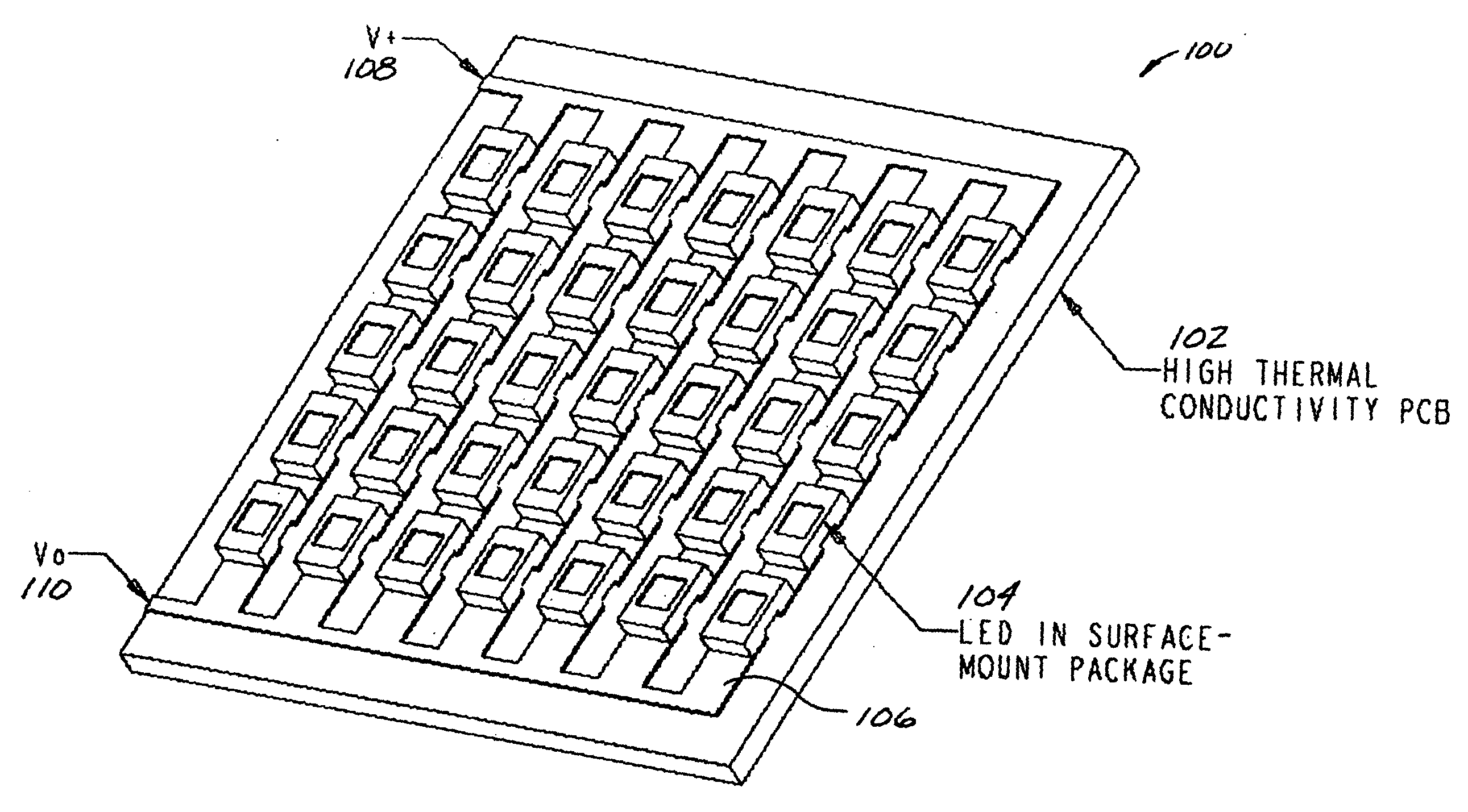
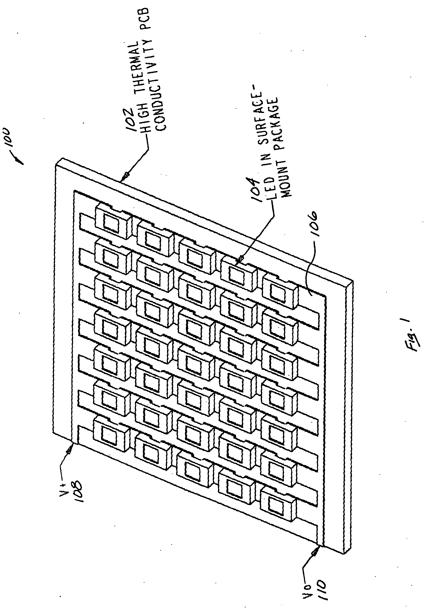
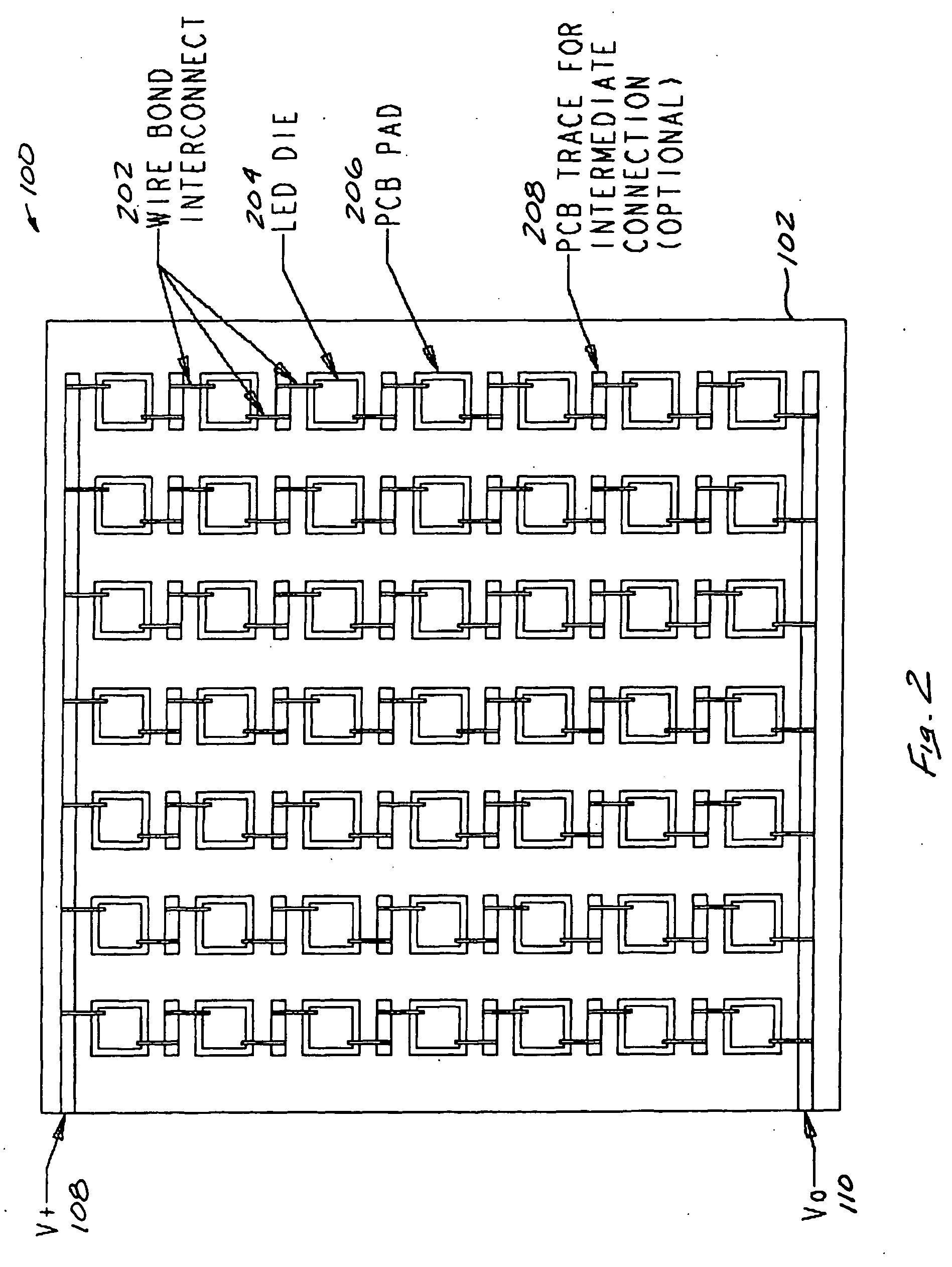
[0030] In general, an LED light engine in accordance with the present invention comprising a high thermal conductivity substrate (e.g., a metal-clad PCB), a plurality of light-emitting-diode (LED) semiconductor devices mechanically connected to the substrate, an outer dike fixed to the substrate and surrounding at least a portion of (preferably all of) the LED devices, and a substantially transparent polymeric encapsulant (e.g., optical-grade silicone) disposed on the plu...


PUM


Abstract

An LED light engine comprising a high thermal conductivity substrate (e.g., a metal-clad PCB), a plurality of light-emitting-diode (LED) semiconductor devices mechanically connected to the substrate, an outer dike fixed to the substrate and surrounding at least a portion of the LED devices, and a substantially transparent polymeric encapsulant (e.g., optical-grade silicone) disposed on the plurality of LED devices and restrained by said outer dike. In one embodiment, the light engine includes a reflector (e.g., a generally conic reflector) fixed to the substrate to form the outer dike. In another embodiment, an optical component (e.g., a lens, filter, or the like) is optically coupled to the polymeric encapsulant disposed on the LED devices.

Description

CROSS REFERENCE TO RELATED APPLICATIONS [0001] This application claims priority of U.S. Provisional Patent Application No. 60 / 507,858 filed Oct. 1, 2003, and 60 / 540,743, filed Jan. 30, 2004, both of which are incorporated herein by reference.FIELD OF THE INVENTION [0002] The present invention generally relates to lighting products and, more particularly, to light engines incorporating light-emitting diodes (LEDs). BACKGROUND OF THE INVENTION [0003] Light emitting diodes (LEDs) have been used for decades in applications requiring relatively low-energy indicator lamps, numerical readouts, and the like. In recent years, however, the brightness and power of individual LEDs has increased substantially, resulting in the availability of 1 watt and 5 watt devices. [0004] While small, LEDs exhibit a high efficacy and life expectancy as compared to traditional lighting products. For example, a typical incandescent bulb has an efficacy of 10-12 lumens per watt, and lasts for about 1000 to 2000...

Claims


Application Information

Patent Timeline
Patent Type & Authority Applications(United States)
IPC IPC(8): F21K99/00F21S4/00F21S6/00F21V5/04F21V7/00F21V7/04F21V7/22F21V21/00F21V23/00F21V29/00H01L25/075H01L33/64
CPCF21K9/00H01L25/0753H01L33/64H01L2224/48227F21Y2101/02F21Y2105/001Y10S362/80F21V7/041F21Y2105/10F21Y2115/10
Inventor CHOU, DER JEOUNELSON, DANIELKULAGA, THOMAS
Owner ENERTRON
Why Eureka
Try Eureka