
Lamp guide device and backlight assembly for liquid crystal display device using the same

a technology of backlight assembly and liquid crystal display, which is applied in the direction of display means, lighting and heating apparatus, instruments, etc., can solve the problems of increased manufacturing costs, large size of crt devices, and heavy weight, and achieve the effect of improving operation and production efficiency

Active Publication Date: 2005-04-07
LG DISPLAY CO LTD
View PDF6 Cites 84 Cited by
  • Summary
  • Abstract
  • Description
  • Claims
  • Application Information

AI Technical Summary

Benefits of technology

[0016] An object of the present invention is to provide a direct-type backlight assembly for an LCD device that prevents separating of a lamp guide from a lower case.
[0017] Another object of the present invention is to provide a direct-type backlight assembly for an LCD device that improves operation and production efficiencies.

Problems solved by technology

However, the CRT devices are large-sized, heavy weight, and require high driving voltages.
However, since the LCD device is not luminescent, it requires an additional light source in order to display the images.
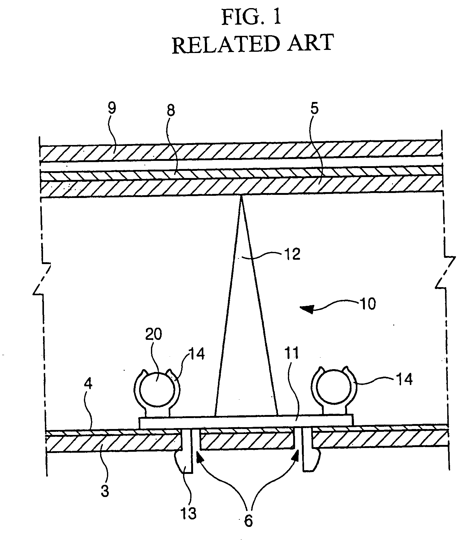
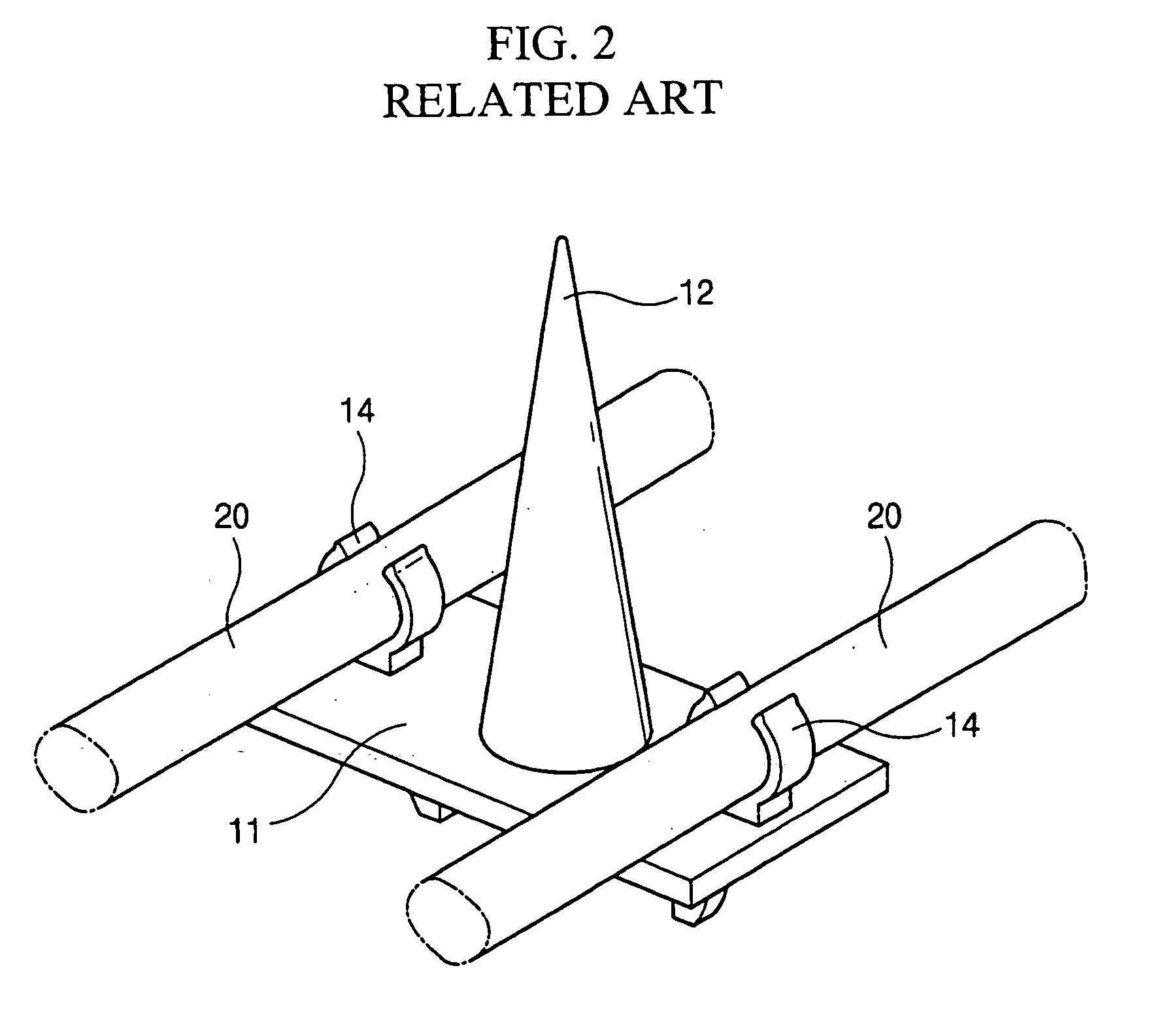
Since a considerable amount of space exists between the lamps and the diffusing plate, the diffusing plate will deform (or sag) due to its weight or will deform due to thermal expansion caused by the heat generated by the lamps.
Furthermore, additional utilization of the adhesive tape or the screw increases manufacturing costs and reduces production efficiency due to an added process of attaching the adhesive tape and / or screw.

Method used


Image

  • Lamp guide device and backlight assembly for liquid crystal display device using the same
  • Lamp guide device and backlight assembly for liquid crystal display device using the same
  • Lamp guide device and backlight assembly for liquid crystal display device using the same

Examples


Embodiment Construction

[0031] Reference will now be made in detail to embodiments of the present invention, which are illustrated in the accompanying drawings.

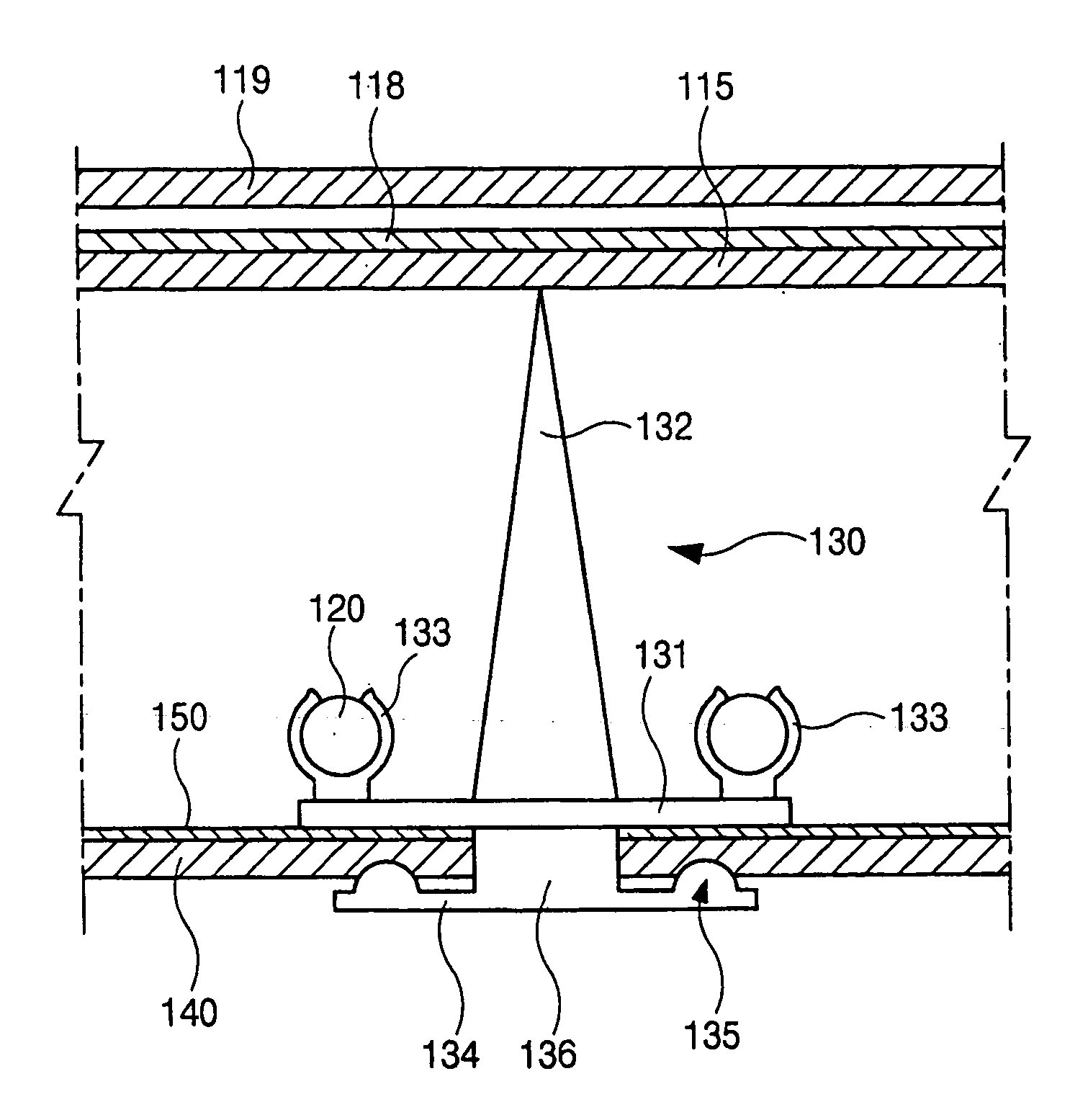
[0032]FIG. 4 is a cross sectional view of an exemplary backlight assembly for an LCD device according to the present invention, and FIG. 5 is a perspective view of the exemplary lamp guide of the backlight assembly of FIG. 4 according to the present invention. In FIGS. 4 and 5, a plurality of lamps 120 may be disposed over an upper surface of a lower case 140, and a lamp guide 130 may be positioned on the upper surface of the lower case 140. In addition, a plurality of optical sheets 115 and 118 and an LCD panel 119 may be sequentially disposed over the lamp guide 130. For example, the plurality of optical sheets 115 and 118 may include diffusing plates and prism sheets.

[0033] The lamp guide 130 may include a plate 131, a sheet supporting portion 132, a lamp holder 133, and a case connector 134. The plate 131 may be disposed parallel to an inner l...


PUM

PropertyMeasurementUnit
sizesaaaaaaaaaa
conical shapeaaaaaaaaaa
cylindrical shapeaaaaaaaaaa

Abstract

A direct-type backlight assembly for a liquid crystal display device includes a lower case, a plurality of lamps disposed over a first surface of the lower case, a plurality of optical sheets disposed over the first surface of the lower case, and a lamp guide disposed on the first surface of the lower case, the lamp guide including a plate parallel to and disposed on the first surface of the lower case, a sheet supporting portion formed on a first surface of the plate to support the optical sheets, a plurality of lamp holders formed on the first surface of the plate to affix the plurality of lamps therein, and a case connector connected to a second surface of the plate and having a plurality of protrusions facing the second surface of the plate.

Description

[0001] The present invention claims the benefit of Korean Patent Application No. 2003-0069461, filed in Korea on Oct. 7, 2003, which is hereby incorporated by reference. BACKGROUND OF THE INVENTION [0002] 1. Field of the Invention [0003] The present invention relates to a backlight assembly for a liquid crystal display (LCD) device, and more particularly, to a direct-type backlight assembly for an LCD device. [0004] 2. Discussion of the Related Art [0005] In general, cathode ray tube (CRT) devices are commonly used as display devices, such as televisions and as monitors for instrumentation systems and information terminal systems. However, the CRT devices are large-sized, heavy weight, and require high driving voltages. Accordingly, flat panel display devices having thin profiles, light weight, and low power consumption have been developed. [0006] The flat panel display devices include LCD devices, plasma display panel (PDP) devices, field emission display (FED) devices, and electro...

Claims


Application Information

Patent Timeline
Patent Type & Authority Applications(United States)
IPC IPC(8): F21V7/04G02F1/13357F21V19/00
CPCF21V19/009G02F2201/54G02F1/133608G02F1/133604G02F1/1335
Inventor KIM, KYOUNG-SUBKIM, SEUNG-HOON
Owner LG DISPLAY CO LTD
Learn More