
Arcuate-shaped inserts for drill bit

a drill bit and insert technology, applied in the field of earth-moving bits, can solve the problems of affecting the resistance of the insert, affecting the performance of the drill bit, and requiring considerable time, effort and expense, and achieving the effect of enhancing the insert's ability to resis

Inactive Publication Date: 2005-04-14
SMITH INT INC
View PDF18 Cites 11 Cited by
  • Summary
  • Abstract
  • Description
  • Claims
  • Application Information

AI Technical Summary

Benefits of technology

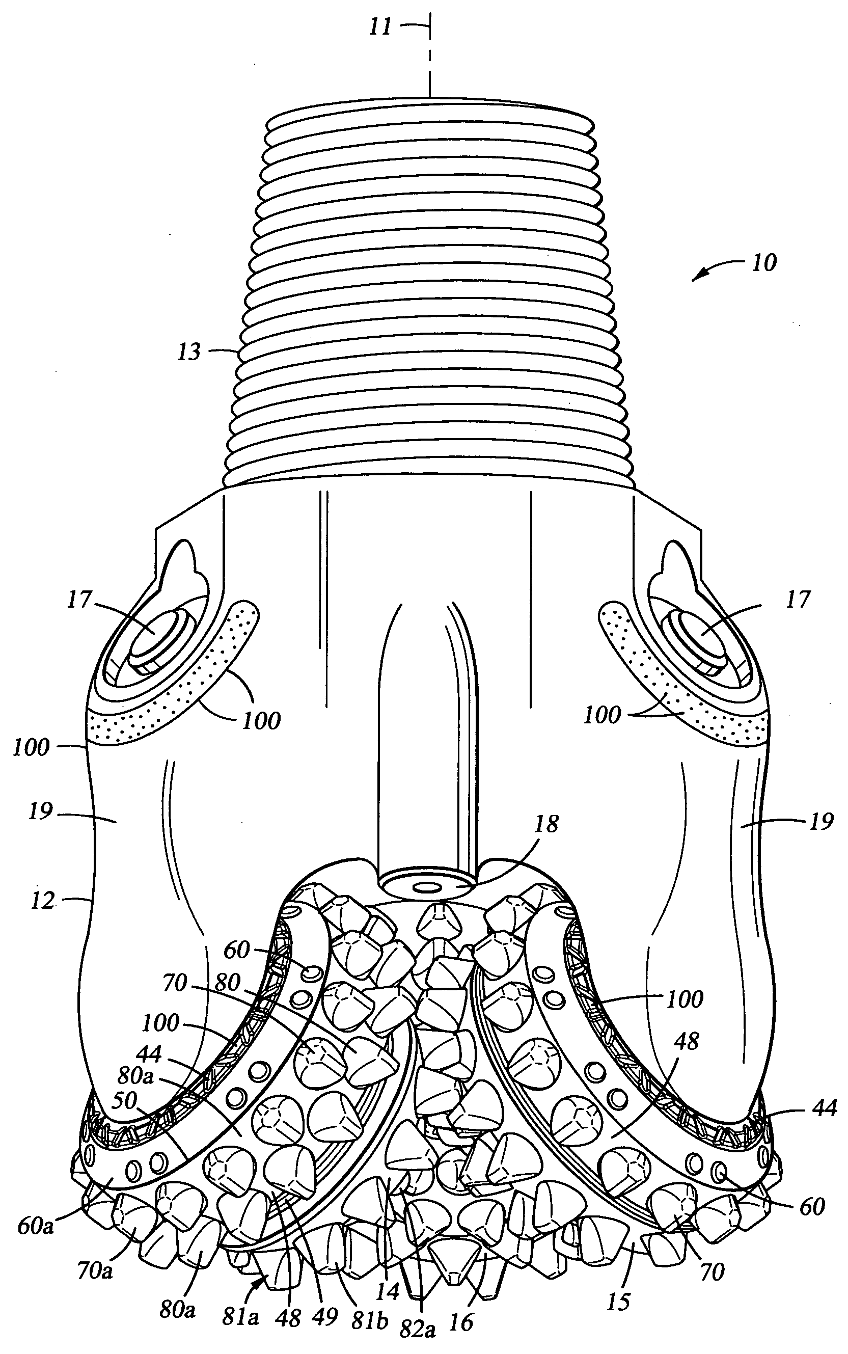
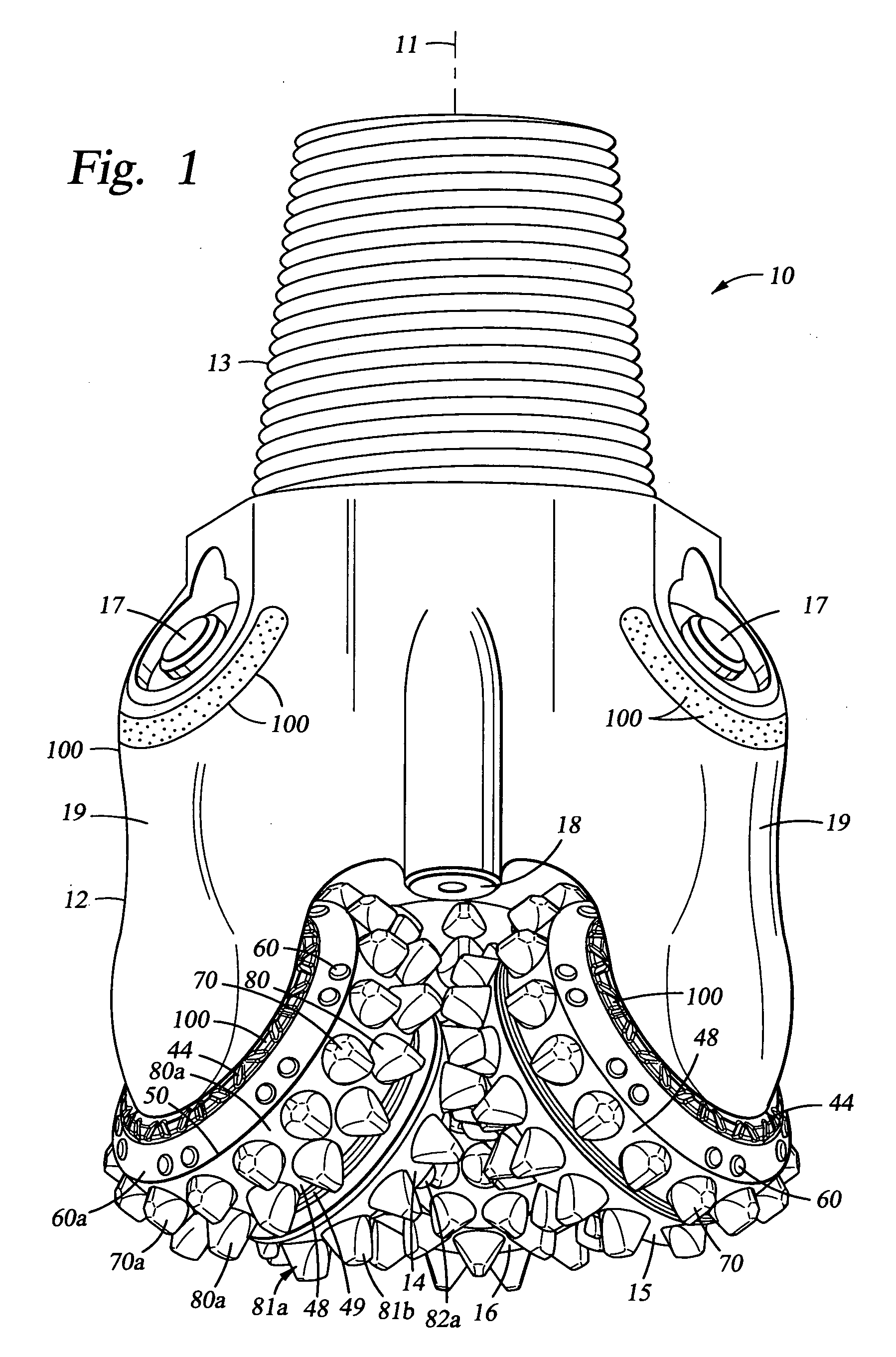
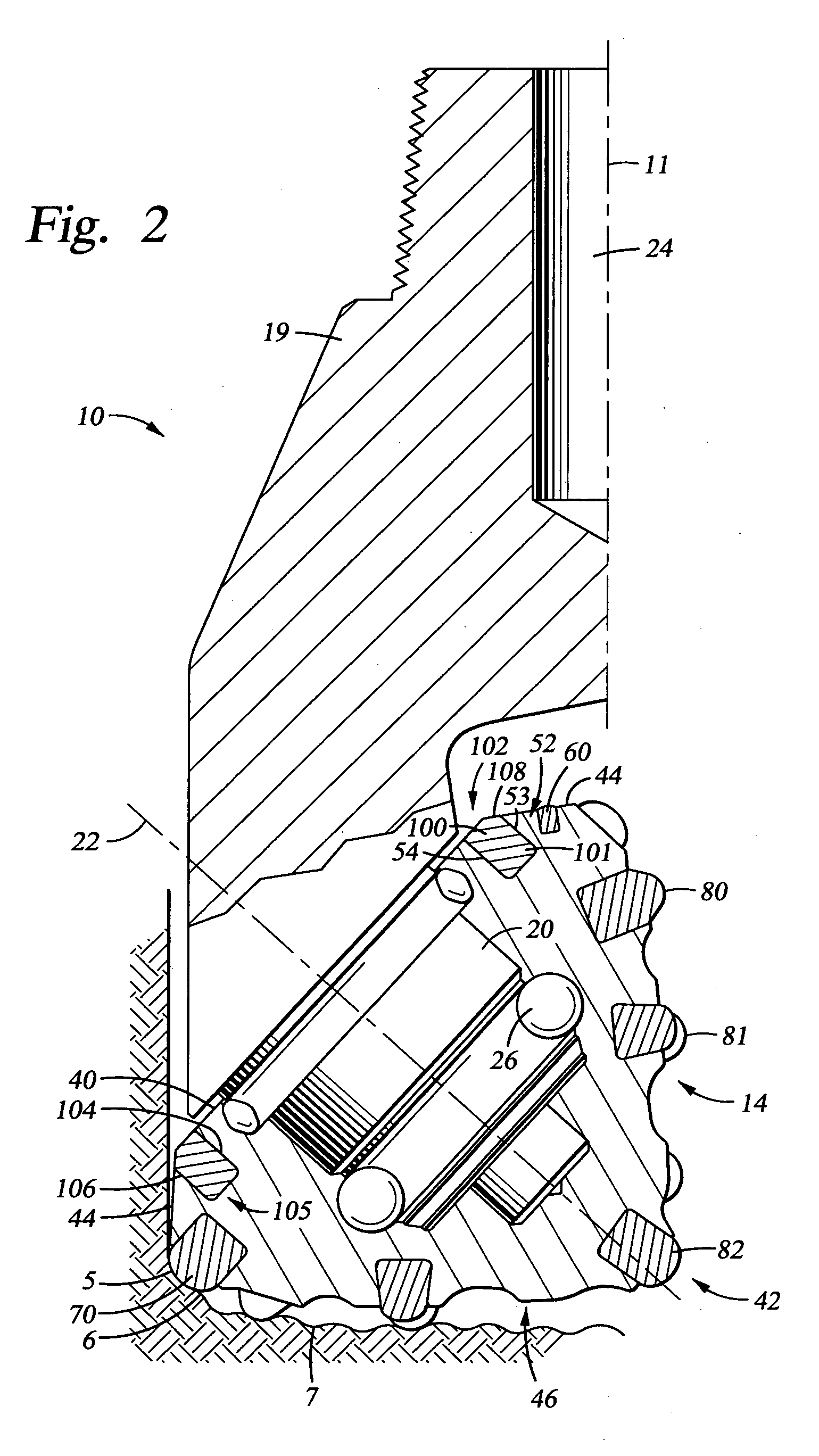
[0013] Preferred embodiments of the invention are disclosed that provide an earth boring bit having enhancements in cutter element design and in manufacturing techniques that provide the potential for increased bit life and footage drilled at full gage, as compared with similar bits of conventional technology. The embodiments disclosed include arcuate-shaped inserts of various arcuate lengths made through a conventional manufacturing process such as HIP. These inserts are disposed within a groove formed in the cone cutter of the rolling cone bit. Such inserts may also be placed in grooves formed elsewhere on the bit.
[0019] The embodiments disclosed further include a variety of features enhancing the inserts' ability to resist rotational movement within the cone groove, such features including non-circular inner surfaces or outer surfaces, tabs, concavities, edges or flats formed on the inner or outer surfaces of the arcuate-shaped inserts that engage similarly shaped features in the cone groove. Engaging pegs and corresponding recesses in the inserts and cone groove may also be employed.
[0020] Providing arcuate inserts in a groove about the entire cone or the major portion thereof, and manufacturing the inserts of extremely hard or durable materials as permitted by HIP technology, overcomes certain problems associated with conventional bits. Specifically, the arcuate inserts extending about the cone surface eliminates the areas in conventional bits between the cylindrical-based inserts that were vulnerable to erosion and premature wear. The bits and rolling cone cutters disclosed in the present application are intended to better protect the material between the extending protrusions of the cutting surface and to better protect against insert breakage and loss. Further, in the embodiments herein disclosed, the heat generated by the cutting surface is better able to be dissipated by virtue of the greater size of the arcuate insert as compared to the conventional, cylindrical-based inserts. This permits the arcuate inserts to retain their desirable material characteristics for a longer period of time whereas with conventional bits, the extreme heat could degrade or deteriorate the insert material. 100211 The bits, rolling cone cutters, and arcuate inserts described herein provide opportunities for greater improvement in cutter element life and thus bit durability and ROP potential. These and various other characteristics and advantages will be readily apparent to those skilled in the art upon reading the following detailed description of the preferred embodiments of the invention, and by referring to the accompanying drawings.

Problems solved by technology

As is thus obvious, this process, known as a “trip” of the drill string, requires considerable time, effort and expense.
Excessive wear of the heel inserts leads to an undergage borehole, loss of cone material that otherwise provides protection for seals, and further results in imbalance of loads on the bit that may cause premature failure of the bit.
One problem with conventional bit designs employing circumferential rows of spaced-apart inserts is that the discontinuous distribution of inserts allows severe wear to take place in the exposed region of the cone cutters between the individual inserts.
Because the portion of the insert that is retained in the cone material is relatively small with conventional inserts having cylindrical bases, loss of adjacent cone material is a significant concern.
This issue is particularly problematic in bits used in hard formations.
As interstitial cone material is worn or eroded away from the regions between the inserts, the cone may lose its ability to absorb impact which, in turn, may lead to insert loss.
Loss of inserts may both decrease ROP, and also lead to further erosion of the steel cone and loss of still additional inserts.
Generally, it would be desirable to include in the heel surface inserts having a relatively large diameter, and to provide the bit with a large number of such heel row inserts; however, the space available for inserts in the heel surface of the cone is severely limited due to the size and number of inserts placed in the gage row of the cone.
The presence of the relatively large gage row inserts limits the size and the number of heel row inserts that can be retained in the adjacent heel surface.
Because the heel row inserts on such conventional bits must therefore be relatively small in size and number, they do not offer the desired optimum protection against wear.
In addition, the relatively small heel row inserts on conventional bits have other limitations: (a) they offer low strength against breakage / chipping caused by impact; (2) they must endure high contact stress while cutting formation material; (3) they possess relatively low capacity for heat dissipation.
These factors contribute substantially to the failure modes of conventional rolling cone bits.

Method used


Image

  • Arcuate-shaped inserts for drill bit
  • Arcuate-shaped inserts for drill bit
  • Arcuate-shaped inserts for drill bit

Examples


Embodiment Construction

[0013] Preferred embodiments of the invention are disclosed that provide an earth boring bit having enhancements in cutter element design and in manufacturing techniques that provide the potential for increased bit life and footage drilled at full gage, as compared with similar bits of conventional technology. The embodiments disclosed include arcuate-shaped inserts of various arcuate lengths made through a conventional manufacturing process such as HIP. These inserts are disposed within a groove formed in the cone cutter of the rolling cone bit. Such inserts may also be placed in grooves formed elsewhere on the bit.

[0014] In certain embodiments, the arcuate-shaped inserts are disposed in an end-to-end relationship within the groove in the cone and substantially fill the cone groove. In other embodiments, the insert is a ring-shaped insert having a 360° arcuate length. In one aspect of the invention, inserts having 360° arcuate length are retained in a cone groove by interference f...


PUM


Abstract

Disclosed are a variety of arcuate-shaped inserts for drill bits, and in particular, for placement in rolling cone cutters of drill bits. The arcuate inserts include 360° or ring-shaped inserts, as well as inserts of smaller arcuate length. The arcuate inserts are suitable for use in all surfaces of the rolling cone cutter, and in other locations in drill bits, and may have specialized cutting surfaces and material enhancements to enhance their cutting duty performance. Certain arcuate inserts may include stress relieving discontinuities such that, upon assembly into the cone or during drilling, the arcuate inserts may fragment in a controlled and predicted manner into shorter arcuate lengths.

Description

[0001] This application is a Continuation-In-Part of U.S. patent application Ser. No. 10 / 189,966 filed Jul. 3, 2002 and entitled Arcuate-Shaped Inserts for Drill Bits.STATEMENT REGARDING FEDERALLY SPONSORED RESEARCH OR DEVELOPMENT [0002] Not applicable. FIELD OF THE INVENTION [0003] The invention relates generally to earth-boring bits used to drill a borehole for the ultimate recovery of oil, gas or minerals. More particularly, the invention relates to rolling cone rock bits and to an improved cutting structure for such bits. Still more particularly, the invention relates to enhancements in cutter elements and in manufacturing techniques for cutter elements and rolling cone bits. BACKGROUND OF THE INVENTION [0004] An earth-boring drill bit is typically mounted on the lower end of a drill string and is rotated by rotating the drill string at the surface or by actuation of downhole motors or turbines, or by both methods. With weight applied to the drill string, the rotating drill bit ...

Claims


Application Information

Patent Timeline
IPC IPC(8): E21B10/16E21B10/50
CPCE21B10/50E21B10/16
Inventor YONG, ZHOUMINIKUS, JIMSINGH, AMARDEEPNGUYEN, QUANKOLACHALAM, SHARATH
Owner SMITH INT INC
Learn More