Motor operated power steering device

a technology of power steering and motor, which is applied in the direction of couplings, vehicle sub-unit features, and slipcouplings, etc., can solve the problems of steering wheel being unusable, motor damage serious, and preventing the operation of the motor, so as to achieve the required level of precision with ease, and prevent the effect of axial orientation

Inactive Publication Date: 2005-04-14
KOYO SEIKO CO LTD
View PDF8 Cites 37 Cited by
  • Summary
  • Abstract
  • Description
  • Claims
  • Application Information

AI Technical Summary

Benefits of technology

[0017] According to the constitution of the presence of the first distinguishing feature of the present invention, a diametric force corresponding to the diametric deformation of the torque setting member is caused to act on the steering shaft and the gear, and thus frictional resistance between the torque setting member and the steering shaft and frictional resistance between the torque setting member and the gear are generated. These two frictional resistances serve to transmit torque between the steering shaft and the gear. The limit torque value is determined in accordance with either one of these frictional resistances. In other words, when the transmission torque between the steering shaft and the gear exceeds the limit torque value, relative slippage is produced either between the torque setting member and the gear or else between the torque setting member and the steering shaft, whichever offers the least frictional resistance. This slippage gives rise to relative rotation between the steering shaft and the gear, that is, the torque limiter effectively functions.
[0030] It is desirable that means for restricting a diametric movement of the gear with respect to the steering shaft is provided at the outsides of the two axial ends of the torque setting member. This configuration makes it possible that the diametric movement, against the diametric force caused by the torque setting member, of the gear with respect to the steering shaft is prevented at the outsides of the two axial ends of the torque setting member. This makes it possible to prevent the axial orientation of the gear from tilting with respect to the axial orientation of the steering shaft. This in turn prevents any change in the backlash and in the degree of engagement between this and other gears, thereby ensuring that there is no change in the feel of the steering.

Problems solved by technology

In a motor operated power steering device which incorporates a steering shaft, a gear fitted around the circumference of the steering shaft, and a motor that transmits its rotational force to the steering shaft by way of the gear for the purpose of assisting the steering operation, the motor is seriously damaged if excessive torque is applied to the steering shaft as a result, for example, of the driver's vehicle mounting a roadside curb.
However, when the torque limiter is incorporated into the motor in this way, it is prevented from functioning if the motor's output shaft is locked for some reason such as the occurrence of an accident.
In this sort of situation, the steering wheel becomes unusable.
Another problem is that the teeth of the gear which transmits the rotational force of the motor to the steering shaft are sometimes made of a synthetic plastic in order to reduce noise.
Teeth of this sort is broken by the application of excessive torque and this causes the gear rotation to lock.
The torque limiter incorporated into the motor does not function under circumstances of this sort and the steering wheel becomes unusable.
Another problem is that in transmission systems in which the rotational force of the motor is transmitted to the steering shaft by way of gears, the efficiency of transmission of the gears tends to vary by the individual difference of the gears.
It is for this reason difficult to set the limit torque value precisely within the predetermined setting range.
The above mechanism which needs a plurality of friction plates to be pinched, however, call for the use of a large number of parts while at the same time increasing the number of man / machine hours required for manufacture of the device.
It is difficult under these circumstances to ensure that the limit torque value is set accurately within the predetermined setting range.
Again, the need for the limit torque value adjustment mechanism also increases the number of parts required and complicates the configuration of the device.
This degree of machining accuracy is in practice difficult to achieve and this makes it difficult to ensure that the limit torque is set precisely within the predetermined setting range.
However, for the mechanism which presses the gear onto the member fitted on the steering shaft via the plural friction plates by the axial force derived from the axial deformation of the spring, a large number of parts are required and a greater number of man / machine hours is required to complete the manufacturing process.
It is difficult under these circumstances to ensure that the limit torque value is set accurately within the predetermined setting range.
Again, the need for the limit torque adjustment mechanism also increases the number of parts required and complicates the configuration of the device.
However, when the rotational force is transmitted to the counterclockwise direction, the gear comes into contact with the member fitted on the steering shaft, so that the gear can not move.

Method used


Image

  • Motor operated power steering device
  • Motor operated power steering device
  • Motor operated power steering device

Examples


Embodiment Construction

[0041] The following section provides a detailed description of the first preferred embodiment of the present invention by reference to FIGS. 1 to 6 below.

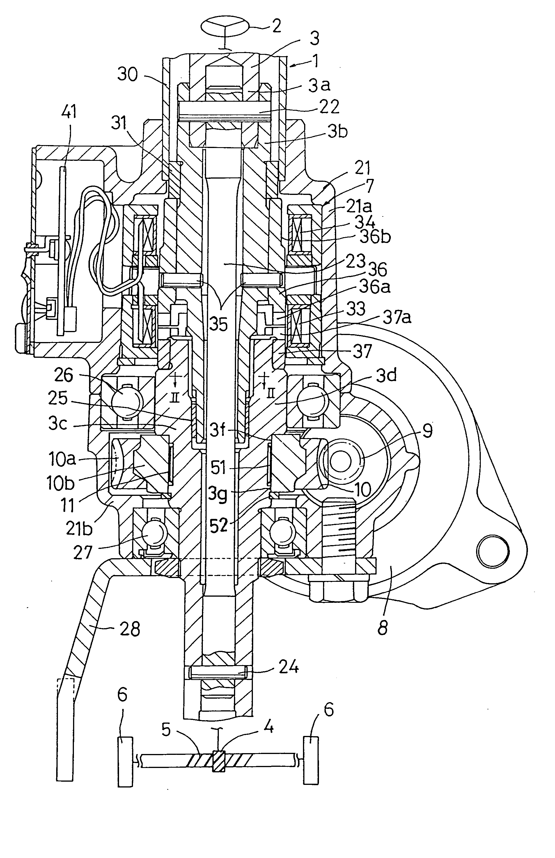
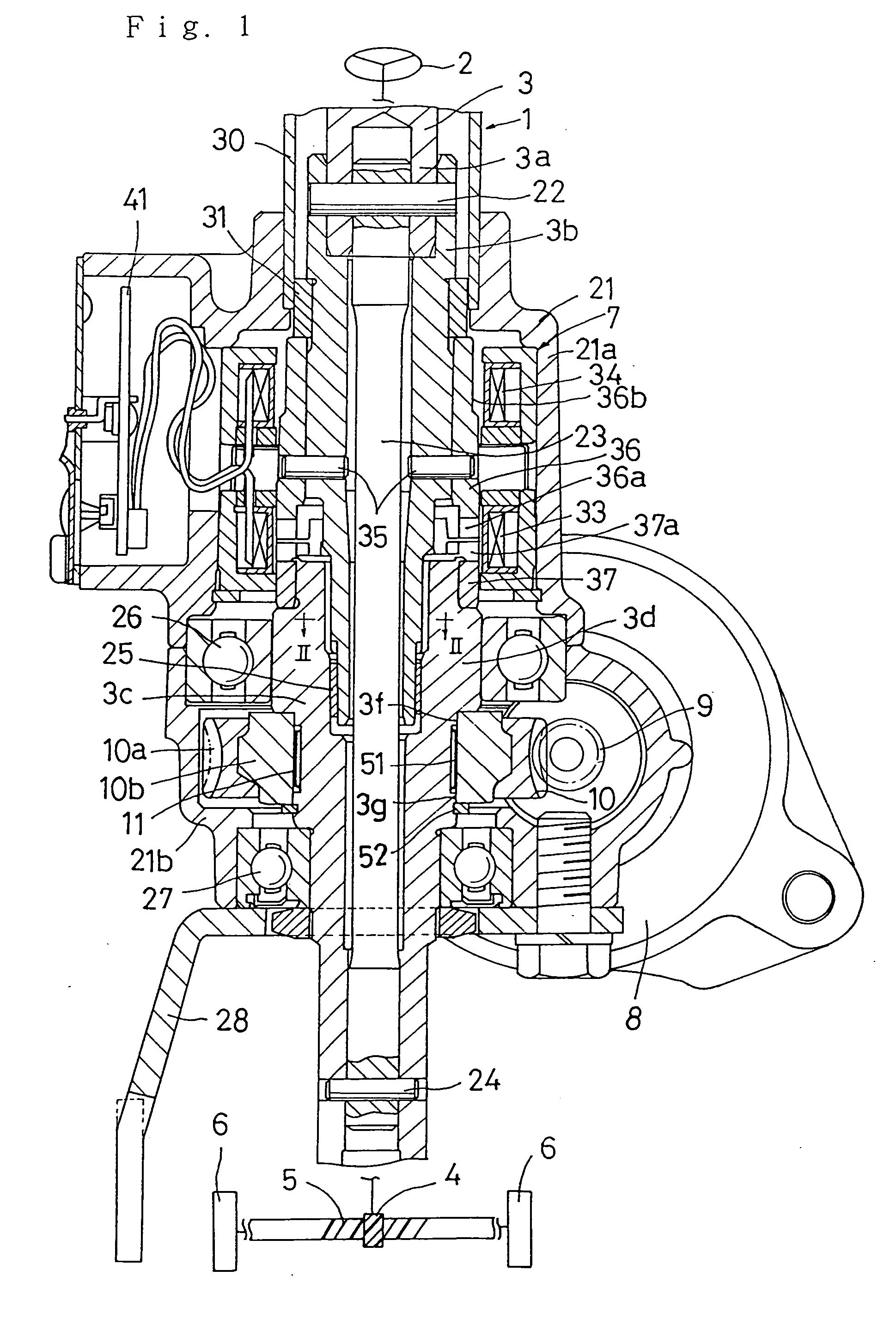
[0042] The motor operated power steering device 1 shown in FIG. 1 transmits steering torque, which is generated by turning the steering wheel 2, by way of a steering shaft 3 to a pinion 4. The transmission of the steering torque causes movement in a rack 5 which meshes with the pinion 4. This varies the steering angle of the road wheels 6 which are linked to the rack 5 by way of tie-rods, knuckle arms, and the like (omitted from the drawing).

[0043] To supply steering assistance force in accordance with the steering torque transmitted by the steering shaft 3, a torque sensor 7, which detects the steering torque, a steering assistance motor 8, which is driven in accordance with the detected steering torque, and a worm 9 and worm wheel 10, whose function is to transmit the rotational force of the motor 8 to the steering shaft 3, ar...


PUM


Abstract

A motor operated power steering device which transmits rotational force from a steering assistance motor to a steering shaft by way of a gear fitted around the outer circumference of the steering shaft. A torque limiter fitted in between the steering shaft and the gear comprises a torque setting member, which is subject to diametric deformation as a result of being fitted in between the outer circumference of the steering shaft and the inner circumference of the gear. Diametric force is applied to the steering shaft and the gear in accordance with the diametric deformation of the torque setting member. The limit torque value of the torque limiter corresponds to the diametric deformation of the torque setting member.

Description

CROSS-REFERENCE TO RELATED APPLICATIONS [0001] The present patent application is a division of application Ser. No. 08 / 635,614, filed Apr. 22, 1996, which is incorporated herein by reference in its entirety.BACKGROUND OF THE INVENTION [0002] 1. Field of the Invention [0003] The present invention relates to a motor operated power steering device which incorporates a torque limiter to combat the application of excessive torque to the steering shaft. [0004] 2. Related Art [0005] In a motor operated power steering device which incorporates a steering shaft, a gear fitted around the circumference of the steering shaft, and a motor that transmits its rotational force to the steering shaft by way of the gear for the purpose of assisting the steering operation, the motor is seriously damaged if excessive torque is applied to the steering shaft as a result, for example, of the driver's vehicle mounting a roadside curb. Again, if output is increased by using the gear to increase the decelerat...

Claims


Application Information

Patent Timeline
Patent Type & Authority Applications(United States)
IPC IPC(8): B62D5/04F16D1/08F16D7/02
CPCB62D5/043F16D7/021F16D1/0835B60Y2410/102B62D3/06B62D3/12
Inventor YAMAMOTO, TATSUHIROTAKAOKA, MANABU
Owner KOYO SEIKO CO LTD
Why Eureka
Try Eureka