Method of determining mass-to-charge ratio of ions and mass spectrometer using the methhod

a technology of mass-to-charge ratio and mass-spectrometer, which is applied in the direction of particle separator tube details, instruments, separation processes, etc., can solve the problem of inability to determine the mass-to-charge ratio, and achieve the effect of reducing the time required for measurement, reducing the range of mass-to-charge ratio, and improving the efficiency of using ions

Active Publication Date: 2005-04-14
SHIMADZU CORP +1
View PDF2 Cites 24 Cited by
  • Summary
  • Abstract
  • Description
  • Claims
  • Application Information

AI Technical Summary

Benefits of technology

The method according to the present invention makes it possible to determine the mass-to-charge ratios of various kinds of ions by carrying out the measurement at least twice. There is no need to limit the range of the mass-to-charge ratio of the ions that are made to repeatedly fly along the loop orbit or reciprocal path. This improves the efficiency of using ions and enables the analysis to cover a broad range of the mass-to-charge ratio even when there is only a small amount of sample available for the analysis. Another advantage is

Problems solved by technology

This is to avoid the situation where ions having flown along the orbit or path different numbers of times and accordingly having different flight distances reach the detector

Method used


Image

  • Method of determining mass-to-charge ratio of ions and mass spectrometer using the methhod
  • Method of determining mass-to-charge ratio of ions and mass spectrometer using the methhod
  • Method of determining mass-to-charge ratio of ions and mass spectrometer using the methhod

Examples


Embodiment Construction

An embodiment of the mass spectrometer according to the present invention is described, referring to the attached drawings.

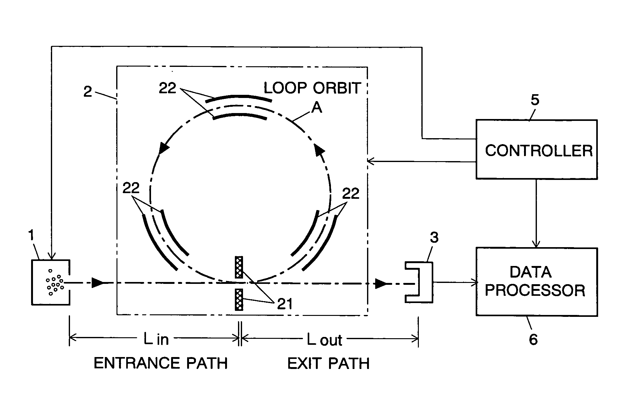
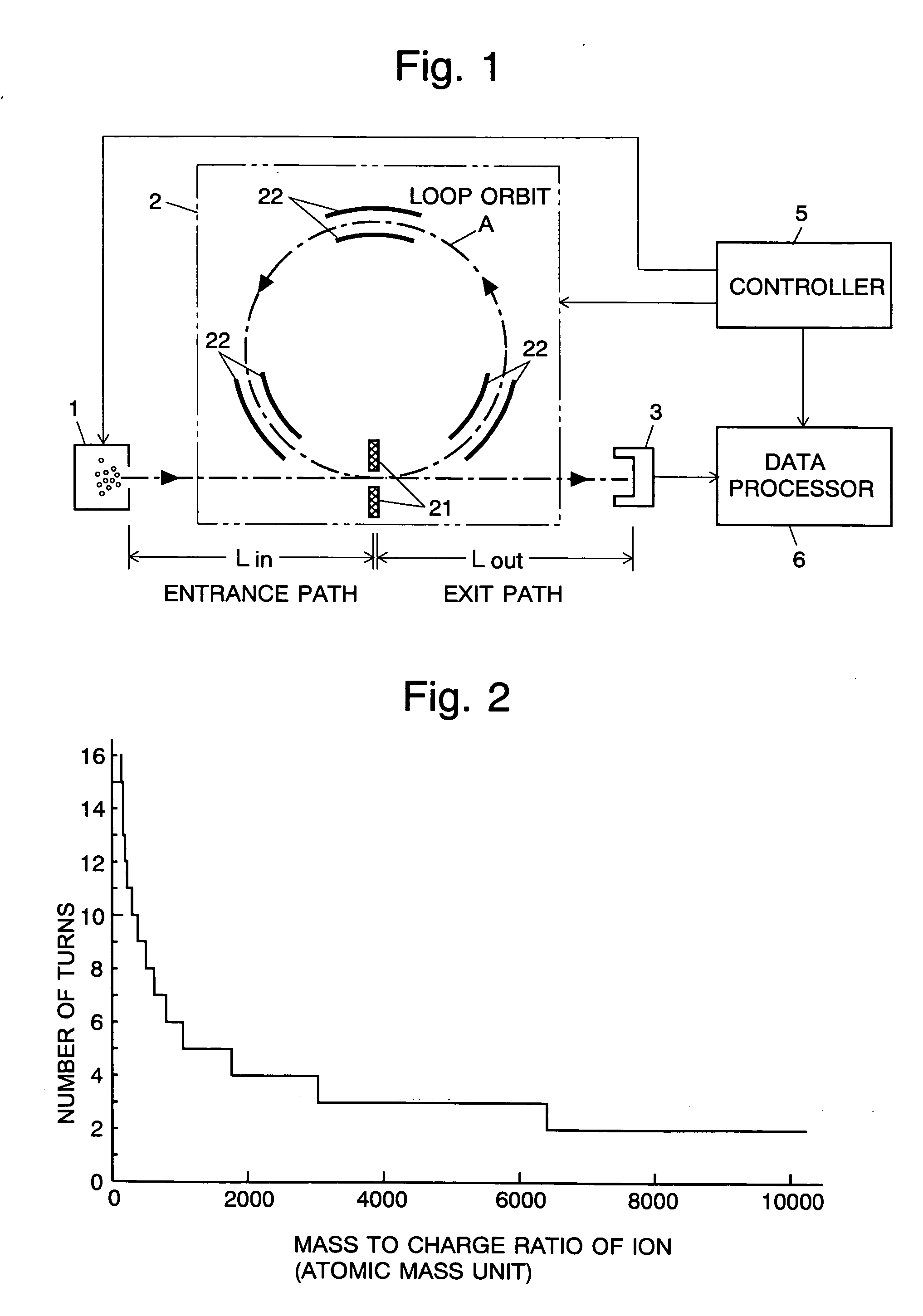
FIG. 1 is a schematic diagram of the mass spectrometer of the present embodiment. In FIG. 1, the ion source 1, the flight space 2 and the ion detector 3 are located inside a vacuum chamber (not shown). The data processor 6 processes the detection signal of the ion detector 3, and the controller 5 controls the flight of the ions and the operation of the data processor 6.

The ion source 1 gives kinetic energy to the ionized molecules, which are the target of the analysis, to inject them into the flight space 2. The molecules may be ionized by any method. When, for example, the mass spectrometer of the present embodiment is used in a gas chromatograph / mass spectrometer (GC / MS), the ion source 1 is constructed to ionize gas molecules by electron impact ionization or chemical ionization. When the mass spectrometer of the present embodiment is used in a liquid chro...


PUM


Abstract

In an analysis using a mass spectrometer having a loop orbit along which ions are made to fly a plurality of times, the present invention provides a method of determining the mass-to-charge ratio of an ion without limiting the range of the mass-to-charge ratio of the ions to be brought into the loop orbit while allowing the lapping of the orbiting ions. The measurement is carried out two or more times under different conditions (Tg=500[μs], 400[μs]) under which the number of turns of the ion concerned is different. Flight times are determined from the flight time spectrums obtained by at least two measurements. Though the numbers of turns themselves are unknown, it is possible to calculate possible mass-to-charge ratios for each flight time by incrementally setting the number of turns at plural values. The two sets of possible mass-to-charge ratios derived from the two flight time values (525[μs], 441[μs]) determined by the two measurements are compared with each other, and a value that is found in both measurement results is selected as the mass-to-charge ratio of the ion concerned. Thus, it is possible to determine the mass-to-charge ratio without limiting the range of the mass-to-charge ratio before the ions are brought into the loop orbit.

Description

The present invention relates to a method of determining the mass-to-charge ratio of ions and, more specifically, to a method of using a mass spectrometer having a flight space in which ions to be analyzed repeatedly fly a loop orbit or a reciprocal path. The present invention also relates to the aforementioned type of mass spectrometer. BACKGROUND OF THE INVENTION In a time of flight mass spectrometer (TOF-MS), ions accelerated by an electric field are injected into a flight space where no electric field or magnetic field is present. The ions are separated by their mass-to-charge ratios according to the flight time until they reach and are detected by a detector. Since the difference of the lengths of flight time of two ions having different mass-to-charge ratios is larger as the flight path is longer, it is preferable to design the flight path as long as possible in order to enhance the resolution of the mass-to-charge ratio of a TOF-MS. In many cases, however, it is difficult t...

Claims


Application Information

Patent Timeline
IPC IPC(8): H01J49/04G01N27/62H01J49/40
CPCH01J49/408
Inventor YAMAGUCHI, SHINICHIISHIHARA, MORIOTOYODA, MICHISATO
Owner SHIMADZU CORP
Why Eureka
Try Eureka