Dual ridge horn antenna

a ridge horn and antenna technology, applied in the field of rf antennas, can solve the problems of difficult improvement of the directivity of the antenna without an increase in the vswr within the frequency range of operation, and the narrow beam of the 3115 antenna is not well suited for this purpose, so as to achieve the effect of small antenna length and small dimension

Active Publication Date: 2005-04-14
ETS-LINDGREN
View PDF11 Cites 37 Cited by
  • Summary
  • Abstract
  • Description
  • Claims
  • Application Information

AI Technical Summary

Benefits of technology

According to another aspect of the invention, an aperture of

Problems solved by technology

Thus, although the standard ridged horn antenna provides usably high gain over a very broad frequency range, its directivity deteriorates at the high frequency end of that range.
This is undesirable in most applications especially when the ridged horn antenna is used for calibration, gain measurements, or EMC testing.
For EMC Immunity or

Method used


Image

  • Dual ridge horn antenna
  • Dual ridge horn antenna
  • Dual ridge horn antenna

Examples


Embodiment Construction

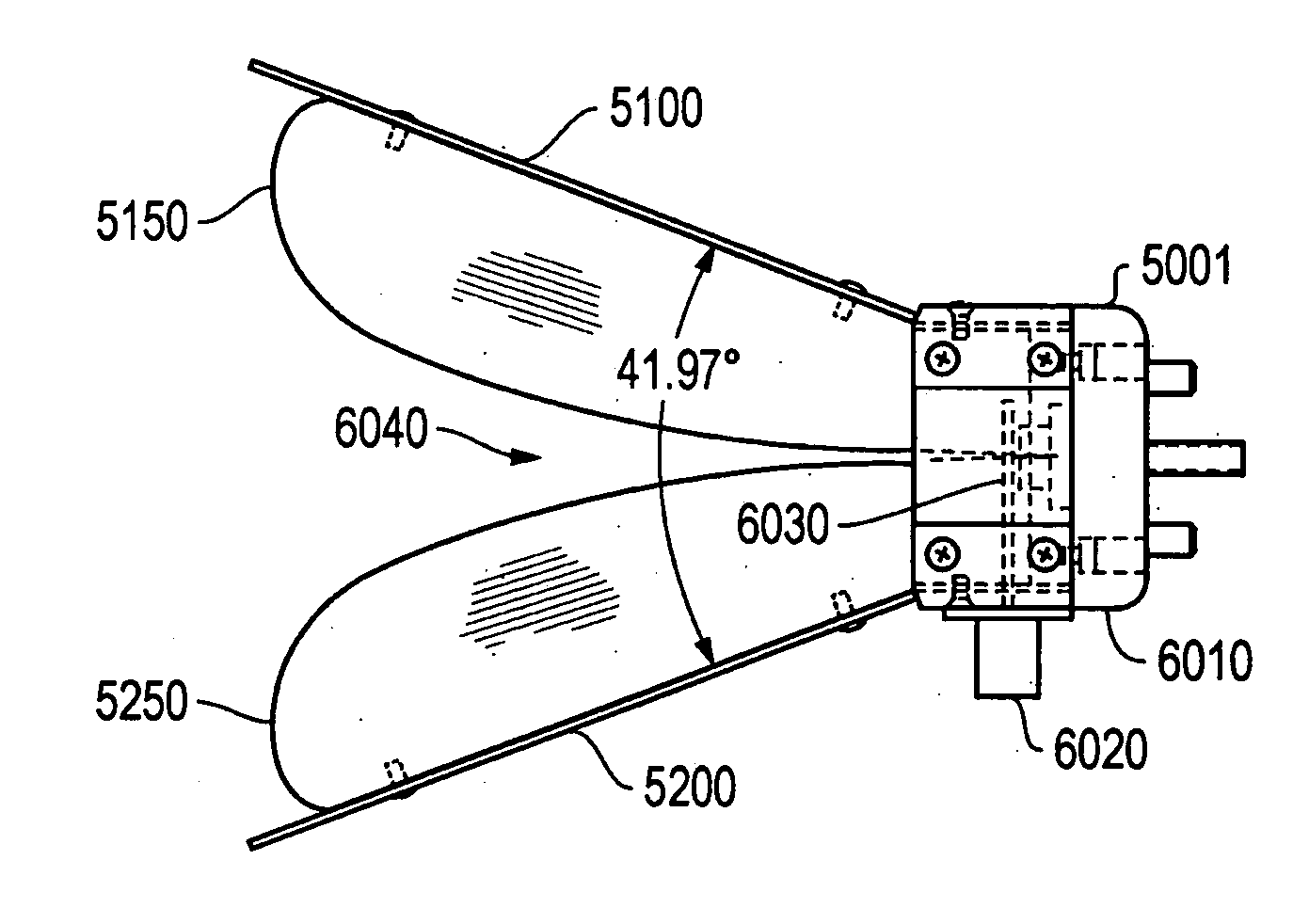
A 3-dimensional view of a preferred embodiment of a ridged horn antenna 5000 of the present invention is shown in FIG. 10. An aperture view is shown in FIG. 11. The embodiment comprises an upper plate 5100 and a lower plate 5200 that are affixed to a cavity assembly 5001. Cavity assembly 5001 is preferably rectangular in cross-section and is open at one end. Affixed to upper plate 5100 is an upper ridge 5150 and affixed to lower plate 5200 is a lower ridge 5250.

A side view of the preferred embodiment of antenna 5000 is shown in FIG. 12, comprising upper plate 5100, lower plate 5200, upper ridge 5150, lower ridge 5250, and cavity assembly 5001. The angle between upper and lower plates 5150 and 5250 is nominally 41.97 degrees in the preferred embodiment as shown in FIG. 12. In a side 6010 of cavity assembly 5001 is a fitting 6020, such as a precision type N jack, to receive a coaxial cable (not shown) to deliver RF power to antenna 5000. The center conductor 6030 of the coaxial feed ...


PUM


Abstract

The present invention provides apparatus and methods for a ridge horn antenna that exhibits improved directivity and main lobe of the radiation pattern at the high end of the frequency range for which its gain remains usably high, while providing a relatively low VSWR across the frequency range of operation.

Description

TECHNICAL FIELD OF THE INVENTION The present invention relates to the field of RF antennas and, in particular, dual ridge horn antennas. BACKGROUND OF THE INVENTION Among the simplest and probably most widely used antennas is the horn, with applications including use as a feed element for dish antennas, reflectors and lenses, as elements of phased array antennas, for calibration and gain measurements of other antennas and devices, and for electromagnetic compatibility (EMC) testing. The widespread applicability of horns arises from its relative simplicity, ease of construction, ease of excitation, versatility, large gain and performance. Horn antennas are essentially flared waveguides that produce a uniform phase front larger than the waveguide itself. A commercially available horn antenna is the Model 3115, manufactured by ETS Lindgren. See http: / / www.ets-lindgren.com / . A three dimensional view of this antenna is shown in FIG. 1. FIG. 2 shows a bottom view, side view and rear vi...

Claims


Application Information

Patent Timeline
IPC IPC(8): H01Q13/02
CPCH01Q13/0275
Inventor RODRIGUEZ, VINCENTE
Owner ETS-LINDGREN
Why Eureka
Try Eureka