Method and apparatus for frequency selective beam forming

a beam forming and frequency selective technology, applied in the field of frequency selective beam forming, can solve the problems of signal-to-noise ratio and interference causing communication disruption, and achieve the effect of improving gain and optimum gain

Inactive Publication Date: 2005-04-14
INTERDIGITAL TECH CORP
View PDF26 Cites 24 Cited by
  • Summary
  • Abstract
  • Description
  • Claims
  • Application Information

AI Technical Summary

Benefits of technology

[0014] In general, the present invention provides a subscriber unit with an ability to transmit and receive signals in different directions simultaneously to allow for optimum gain in both direction

Problems solved by technology

Further, the TX and RX signals bend around objects external from the office building at different angles, which can be another source of difference in transmission paths.
T

Method used


Image

  • Method and apparatus for frequency selective beam forming
  • Method and apparatus for frequency selective beam forming
  • Method and apparatus for frequency selective beam forming

Examples


Embodiment Construction

[0037] A description of preferred embodiments of the invention follows.

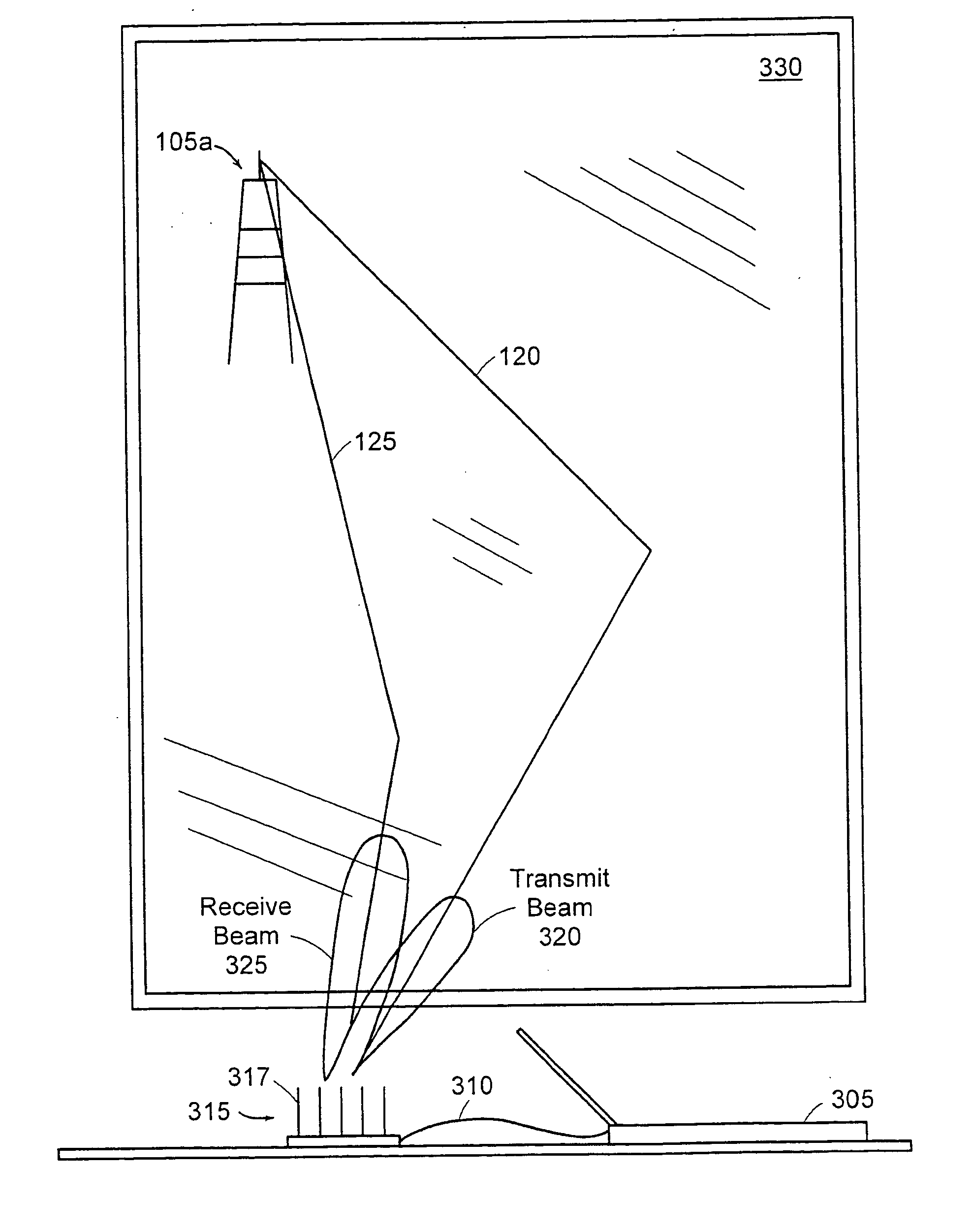
[0038]FIG. 3 is a diagram illustrating an example usage of the present invention. A portable personal computer 305 is coupled via an antenna cable 310 to an antenna array 315. The antenna array 315 is capable of forming a directive beam due to the spacing of the antenna elements 317.

[0039] As shown, the antenna array 315 provides two beams: a transmit beam 320 and a receive beam 325. The transmit beam 320 is directionally pointed to transmit a signal 120 through a window 330 to an antenna tower 105a in an optimal direction. Similarly, the receive beam 325 is directionally pointed to receive a receive beam 125 from the antenna tower 105a through the window 330 in an optimal direction.

[0040] In the case of CDMA for a subscriber unit, transmit (TX) signals operate at 1850-1910 MHZ and receive (RX) signals operate between 1930-1990 MHZ. The difference in frequencies between these two signals is enough to cause, fo...


PUM


Abstract

A directive antenna having plural antenna elements is arranged in a parasitic antenna array. Frequency selective components are connected to an active antenna element. Weighting structures are connected to passive antenna elements positioned substantially equidistant from the active antenna element. The active and passive antenna elements are connected by a space-fed power distribution system to produce independently steerable beams having spectrally separated signals.

Description

RELATED APPLICATION(S) [0001] This application is a continuation of U.S. application Ser. No. 10 / 234,036, filed Aug. 30, 2002, which is a continuation-in-part of U.S. application Ser. No.: 09 / 879,807, filed Jun. 12, 2001, now U.S. Pat. No. 6,448,938. The entire teachings of the above applications are incorporated herein by reference.BACKGROUND OF THE INVENTION [0002] In the area of wireless communications, time division multiple access (TDMA) and code division multiple access (CDMA) protocols are used for communicating from a base station to a mobile station. The TDMA technology uses a single frequency for transmitting and receiving signals, while the CDMA systems use one frequency band for transmitting signals and another frequency band for receiving signals. In both cases, multipath can be a source of interference. [0003]FIG. 1 is an example environment 100 in which multipath is typically present. The environment 100 includes a first antenna tower 105a and a second antenna tower 1...

Claims


Application Information

Patent Timeline
IPC IPC(8): H01Q3/30H01Q1/24H01Q3/26H01Q3/36H01Q3/46H01Q5/00H01Q21/00H01Q25/00H04B7/06H04B7/08H04B7/10
CPCH01Q1/246H01Q3/26H01Q3/36H01Q3/46H04B7/086H01Q21/30H01Q25/00H04B7/0617H01Q21/0018H01Q21/00H01Q1/50
Inventor CHIANG, BINGGAINEY, KENNETH M.PROCTOR, JAMES A. JR.
Owner INTERDIGITAL TECH CORP
Why Eureka
Try Eureka