
Dispersive element, diffraction grating, color display device, demultiplexer, and diffraction grating manufacture

Inactive Publication Date: 2005-04-14
IBM CORP
View PDF5 Cites 91 Cited by
  • Summary
  • Abstract
  • Description
  • Claims
  • Application Information

AI Technical Summary

Benefits of technology

Therefore, an aspect of the present invention is to provide a transmission grating as a dispersive element which can enhance diffraction efficiency and considerably reduce manufacturing costs.
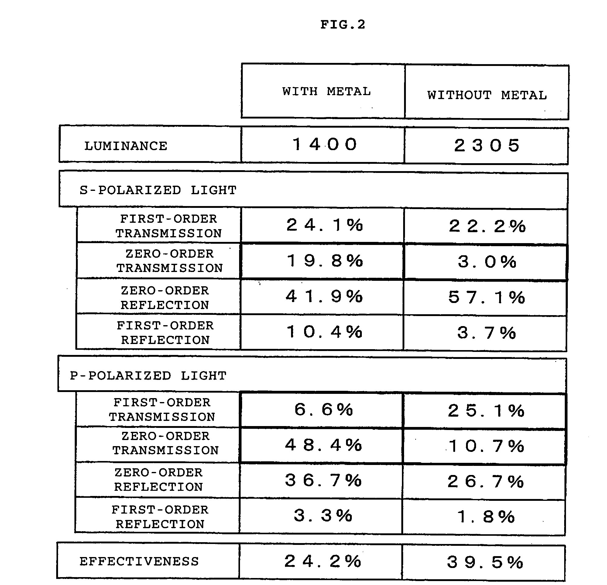
Another aspect of the present invention is to considerably enhance the diffraction efficiency by suppressing zero-order transmitted diffracted light as much as possible and actively utilizing first-order diffracted light.
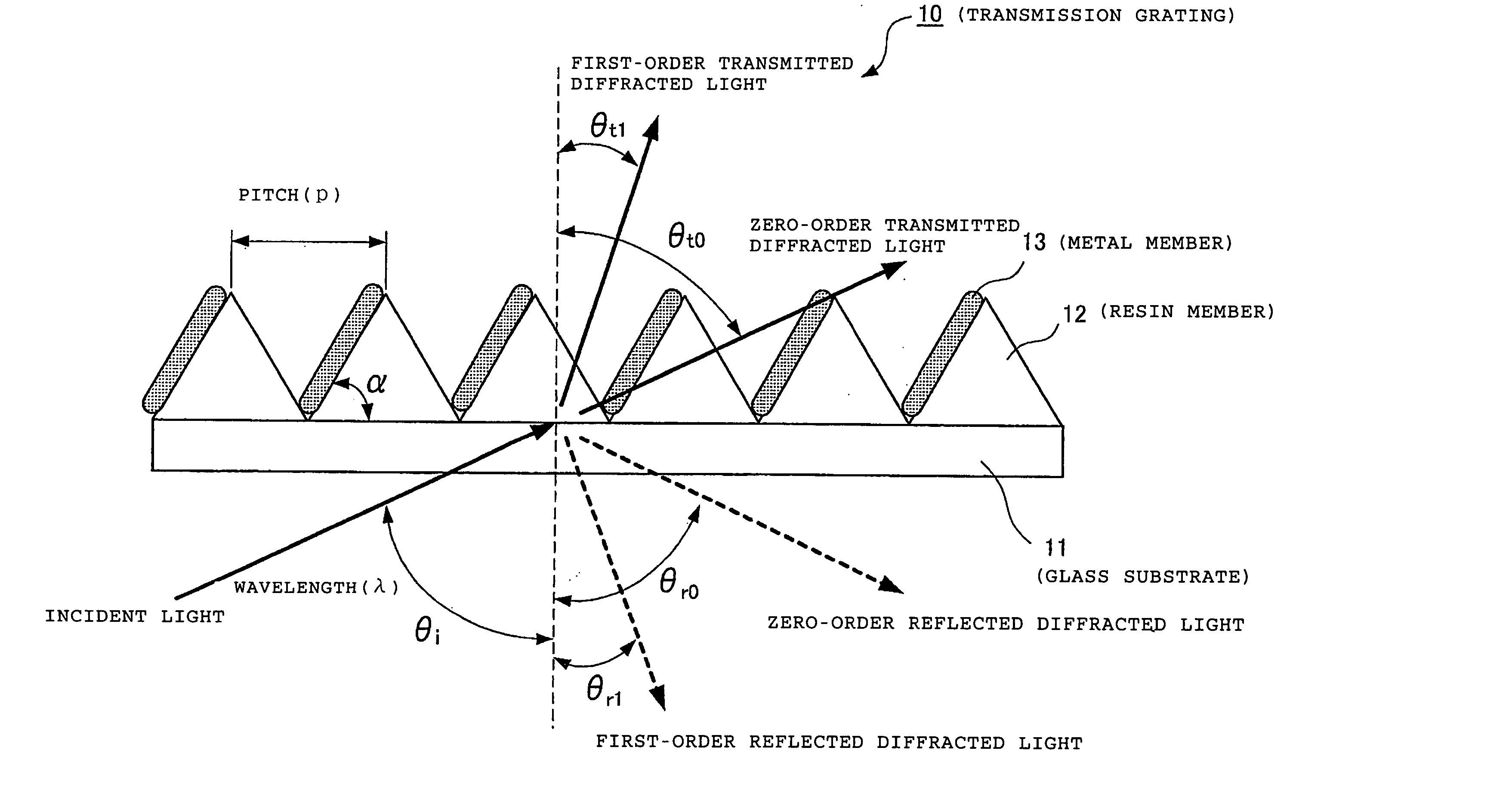
A diffraction grating adopting the present invention includes a resin layer; and a plurality of metal surfaces provided inside the resin layer, the metal surfaces being arranged periodically each of which has an inclination of a given blaze angle from a film surface. Here, it is preferable in light of capability of considerably enhancing the diffraction efficiency when the given blaze angle of the metal surface is determined so as to suppress zero-order transmitted light and to enhance diffraction efficiency of first-order transmitted light with respect to incident light.

Problems solved by technology

Accordingly, the use of the wire grid polarizer is limited to a linear polarizer for infrared rays, for example.
This is because an increase in the width of the metal thin line causes a decline in efficiency as the polarizer due to an increase in intensity of first-order diffracted light.
Accordingly, there are numerous manufacturing processes, and an obtained diffraction grating is very expensive.
However, first-order diffraction efficiency of a transmission grating of the blazed type is limited to about 20% at the maximum.
Accordingly, when the efficiency is raised for a specific wavelength, a trouble arises in a device dealing with a multi-color light source such as a display because the efficiency of other wavelengths is reduced.
However, the zero-order diffracted light not only deteriorates utilization efficiency of the light but also incurs stray light for other optical devices located in the vicinity, and thereby causing a problem in terms of a device layout and accuracy.
However, such an optimal shape is complicated and delicate.
Such a diffraction grating member is difficult to process, or even if processed, applicable process costs will be enormous.
It is not possible to reduce the zero-order diffracted light and to enhance the diffraction efficiency when this element is used as the diffraction grating.
Therefore, it is not possible to achieve enhancement of the diffraction efficiency by reducing the zero-order transmitted light in the diffraction grating as the dispersive element.
Moreover, although the metal is obliquely evaporated according to Patent Document 1, the technique of Patent Document 1 is intended to be used as photoresist but is not designed for use in the diffraction grating as the dispersive element.
Therefore, even if the technique according to Patent Document 1 is adopted, it is not possible to achieve enhancement of the diffraction efficiency by reducing the zero-order diffracted light.
Accordingly, this technique has a difficulty in achieving a performance required in recent years as the diffraction grating to be used in the dispersive element.

Method used


Image

  • Dispersive element, diffraction grating, color display device, demultiplexer, and diffraction grating manufacture
  • Dispersive element, diffraction grating, color display device, demultiplexer, and diffraction grating manufacture
  • Dispersive element, diffraction grating, color display device, demultiplexer, and diffraction grating manufacture

Examples


Embodiment Construction

The present invention provides a transmission grating as a dispersive element which can enhance diffraction efficiency and considerably reduce manufacturing costs. It also considerably enhances the diffraction efficiency by suppressing zero-order transmitted diffracted light as much as possible and actively utilizing first-order diffracted light.

An example embodiment having a dispersive element adopting the present invention includes: a diffraction grating, being composed of a plurality of diffraction grating members having a cross-sectional shape respectively surrounded by any of two straight lines and a curved line; and a plurality of light-shielding members, each being formed on corresponding one of the diffraction grating members at one side of the diffraction grating member along any of the straight line and the curved line of the cross-sectional shape. Here, this light-shielding member is preferably configured to reduce zero-order transmitted light and to enhance diffractio...


PUM


Abstract

In a transmission grating as a dispersive element, diffraction efficiency is enhanced and manufacturing costs are considerably reduced. A dispersive element includes resin members for forming a diffraction grating, being composed of a plurality of diffraction grating members having a cross-sectional shape respectively surrounded by two straight lines such as a triangular shape, and metal members as light-shielding members each being formed on corresponding one of the diffraction grating members at one side of the diffraction grating member along any of the straight line and the curved line of the cross-sectional shape of the diffraction grating member formed by the resin member. The metal members are configured to reduce zero-order transmitted light with respect to incident light, and to enhance diffraction efficiency of first-order transmitted light.

Description

BACKGROUND OF THE INVENTION The present invention generally relates to dispersive elements and the like, and more specifically to dispersive elements and the like such as transmission gratings used in optical instruments. Diffraction gratings are used in various optical instruments. Specifically, many diffraction gratings are used in spectrometers, wave filters and the like to utilize sharp dispersion characteristics thereof. Moreover, it is possible to manufacture the diffraction gratings while arbitrarily determining pitches thereof. Accordingly, a diffraction grating is sometimes used as an angle changing element, a light separating and mixing element or the like in an instrument using a light source such as a laser. The application of the diffraction grating also spreads to the field of displays where light is used as a means of expression instead of a means of communication. There are already numerous basic researches and implementation examples involving the diffraction gra...

Claims


Application Information

Patent Timeline
IPC IPC(8): G02B6/42G02B5/18G02B5/30G02B6/02G02B6/34
CPCG02B5/1814G02B5/1866G02B6/4215G02B6/0053G02B6/29323G02B5/3058G02B6/4213
Inventor TAIRA, YOICHINAKANO, DAIJU
Owner IBM CORP
Learn More