Method for coating multiple stents

a technology for stents and coatings, applied in the field of holding stents, can solve the problems of inability to administer therapeutics to the target site in a uniform and homogenous manner, inability to maintain the effectiveness of injectables, and inability to achieve uniform and homogenous treatment. , to achieve the effect of improving the utilization rate of coating materials, prolonging the exposure to coating spray, and facilitating stent handling

Active Publication Date: 2005-04-14
BOSTON SCI SCIMED INC
View PDF10 Cites 185 Cited by
  • Summary
  • Abstract
  • Description
  • Claims
  • Application Information

AI Technical Summary

Benefits of technology

[0009] A number of alternative embodiments for performance of the method of the present invention are envisioned. For example, there may be a number of alternative embodiments for performing the stent placement step, such as providing stents pre-mounted on stent holders with rotating pins equipping with corresponding stent holder receivers to facilitate stent handling by automated stent placement equipment. Similarly, in the step of applying the coating material, rather than spraying the coating material perpendicularly across the endless belt, the coating may be applied from a sprayer aligned with the major axis of the endless belt such that the rolling stents have a longer exposure to the coating spray. The sprayer may also apply the coating while the spray head is rotating about the line of rolling stents. In a further embodi...

Problems solved by technology

When the amount of coating is depleted the implant's effectiveness may be compromised and additional risks may be inured into the procedure.
For example, when the coating of the implant includes a therapeutic, if some of the coating were removed during deployment, the therapeutic may no longer be able to be administered to the target site in a uniform and homogenous manner.
Similarly, if the therapeutic is ripped from the implant it can reduce or slow dow...

Method used


Image

  • Method for coating multiple stents
  • Method for coating multiple stents
  • Method for coating multiple stents

Examples


Embodiment Construction

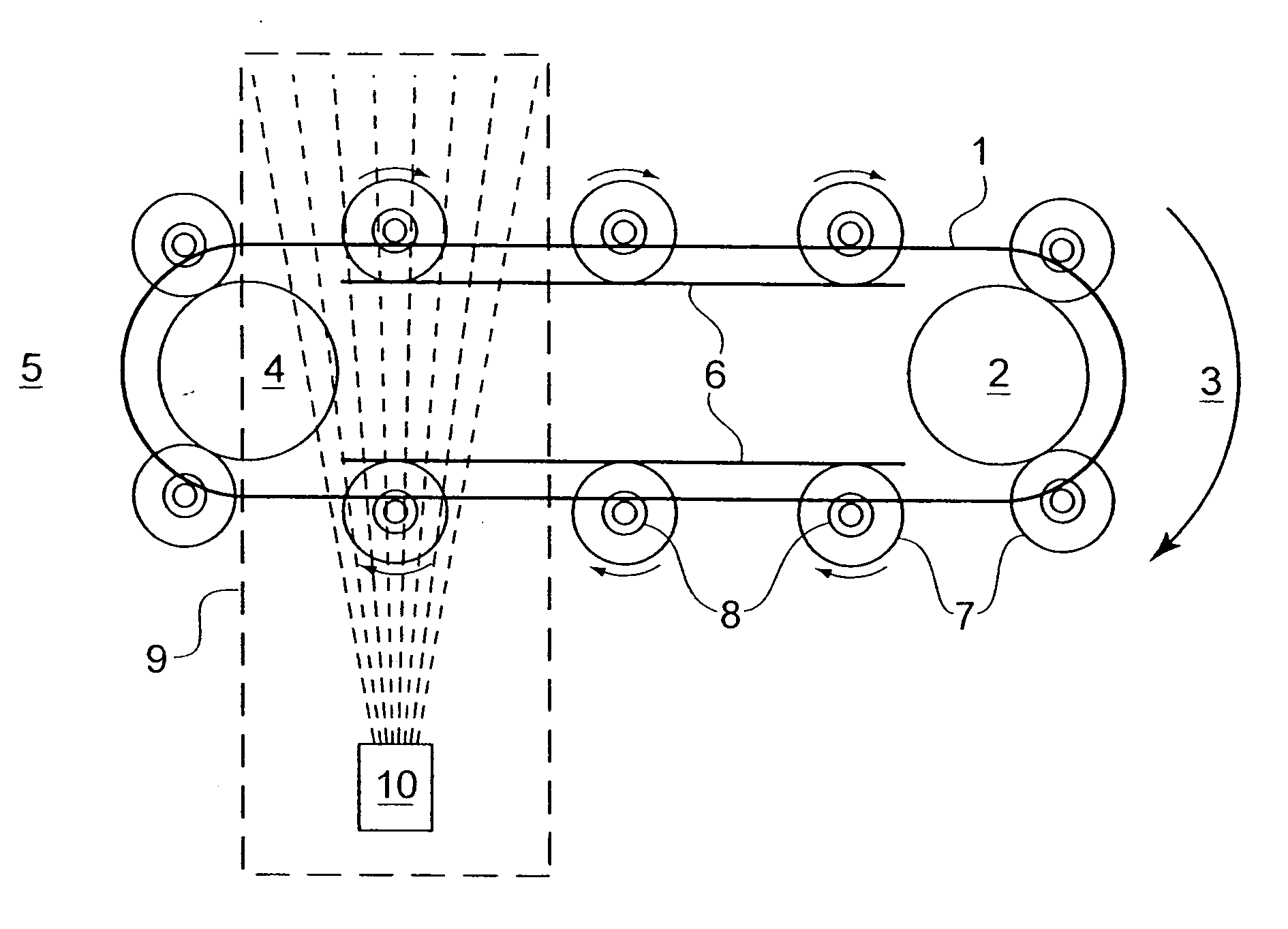
[0018] The present invention is directed to a method for overcoming the foregoing disadvantages by applying a stent coating to stents that are being rolled about their longitudinal axis, where the stents are loaded onto rotating holders affixed to a conveyer, and the conveyer carries the rotating stents and holders through a coating applicator one or more times.

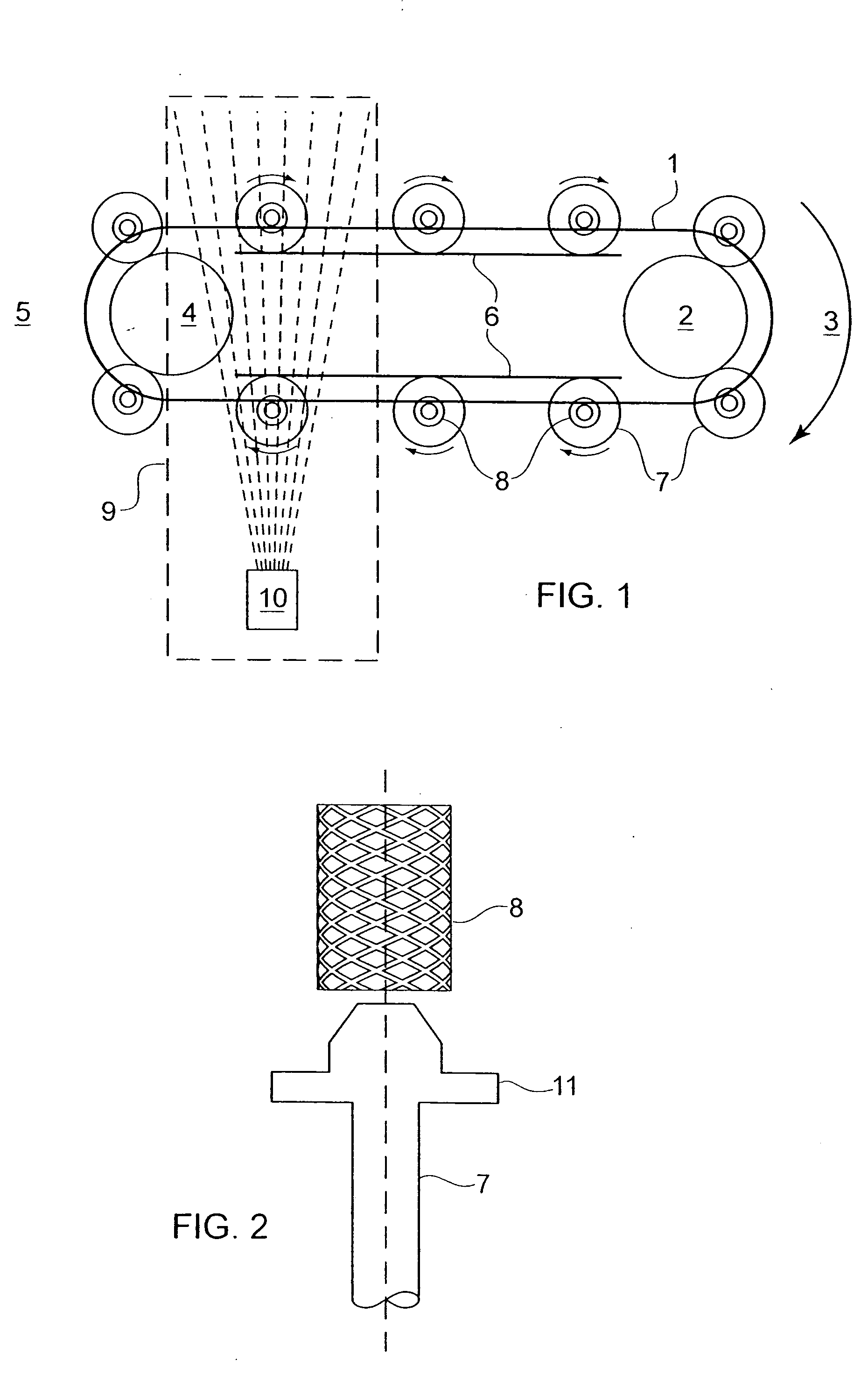
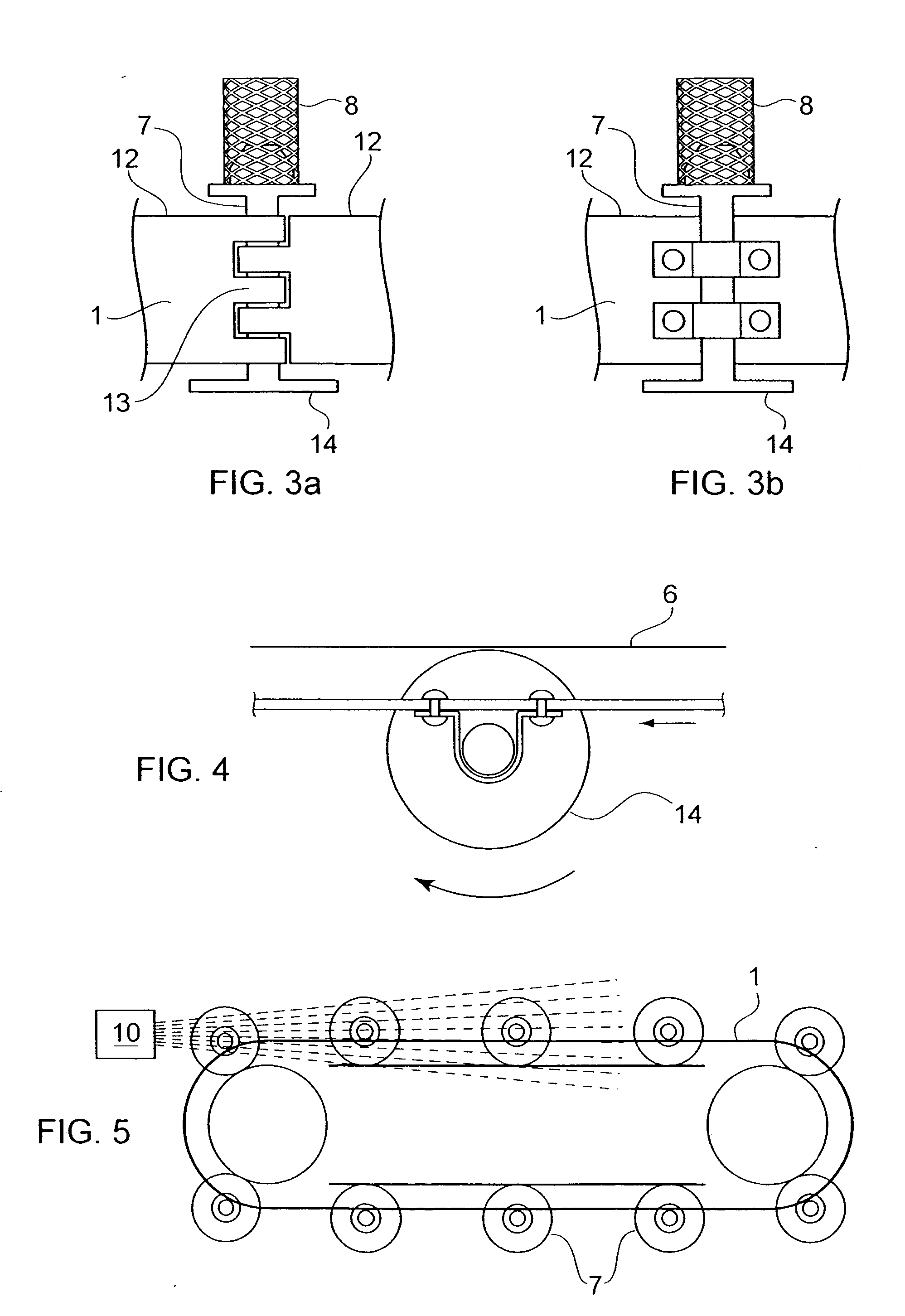
[0019] The method of the present invention in a first embodiment is as follows. In this first embodiment, a conveyer in the form of an endless belt 1 is arranged around a first pulley 2 at a first end 3 of the belt and a second pulley 4 at a second, opposite end 5 of the belt. Endless belt 1 may be advanced by rotating either pulley 2 or pulley 4. Backing plates 6 are provided in the region between pulleys 2 and 4. The backing plates, which can be located adjacent to either the inner or outer face of the belt, are arranged to contact outer peripheral edges of rotating pins 7 mounted on endless belt 1 (details of rotating pin...


PUM

PropertyMeasurementUnit
Distanceaaaaaaaaaa

Abstract

An improved method for high-volume production of coated stents with highly uniform stent coatings using a roll coating technique is provided. In a first embodiment, uncoated stents are placed onto rotating stent holders with automated stent handling equipment. The holders are mounted on an endless conveyer belt which advances the stents toward a stent coater. As the stents advance through the coater, the holders rotate, thereby rolling the stents about their longitudinal axes as coating material is sprayed toward them, ensuring the stents are uniformly coated on their exterior and interior surfaces. After the conveyer turns to carry the coated stents back toward the loading area, the rotating stents pass again through the coating spray, downstream of the initial coating location, thereby increasing the efficient utilization of the coating material. The conveyer then advances the coated stents to an unloading area for removal before the holders return to the stent loading area to receive new stents.

Description

FIELD OF THE INVENTION [0001] The present invention generally regards the holding of stents during manufacture to enable the application of therapeutic and / or protective coatings. More specifically, the present invention pertains to a method for high-throughput, efficient and uniform coating of stents, wherein the stents placed on rotating fixtures on a conveyer, and the conveyer passes the rotating stents through a coating spray or immersion bath to apply a coating to the stents. BACKGROUND [0002] Medical implants are used for innumerable medical purposes, including the reinforcement of recently re-enlarged lumens, the replacement of ruptured vessels, and the treatment of disease such as vascular disease by local pharmacotherapy, i.e., delivering therapeutic drug doses to target tissues while minimizing systemic side effects. Such localized delivery of therapeutic agents has been proposed or achieved using medical implants which both support a lumen within a patient's body and plac...

Claims


Application Information

Patent Timeline
IPC IPC(8): A61L31/08B05B13/02B05C3/10B05D1/00B05D1/02
CPCA61L31/08B05B13/0235B05D2258/00B05D1/002B05D1/02B05C3/10
Inventor PALASIS, MARIANAIMARK, WENDYMICKLEY, TIMFREYMAN, TOBY
Owner BOSTON SCI SCIMED INC
Why Eureka
Try Eureka