

Scanning microscope system
a scanning microscope and microscope technology, applied in the field of scanning microscope systems, can solve problems such as observation position shifts
- Summary
- Abstract
- Description
- Claims
- Application Information
AI Technical Summary
Benefits of technology
Problems solved by technology
Method used
Image

Examples
first embodiment
[0028] In a first embodiment, an image is acquired with an optical microscope, a region in which a pixel group forming the acquired image has great brightness is registered as a region in which there is a substance to be observed, and the registered region is observed with a scanning microscope.
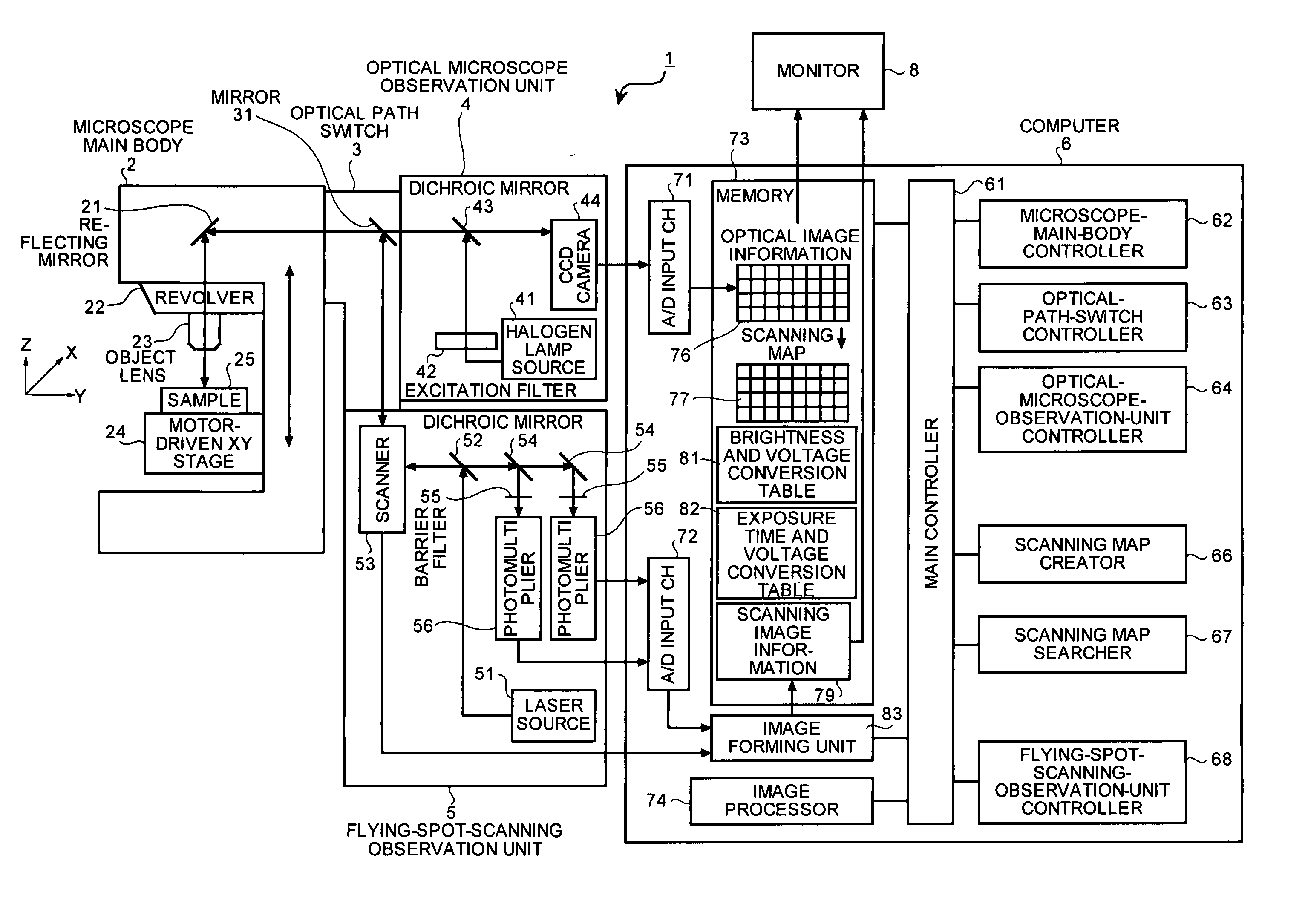
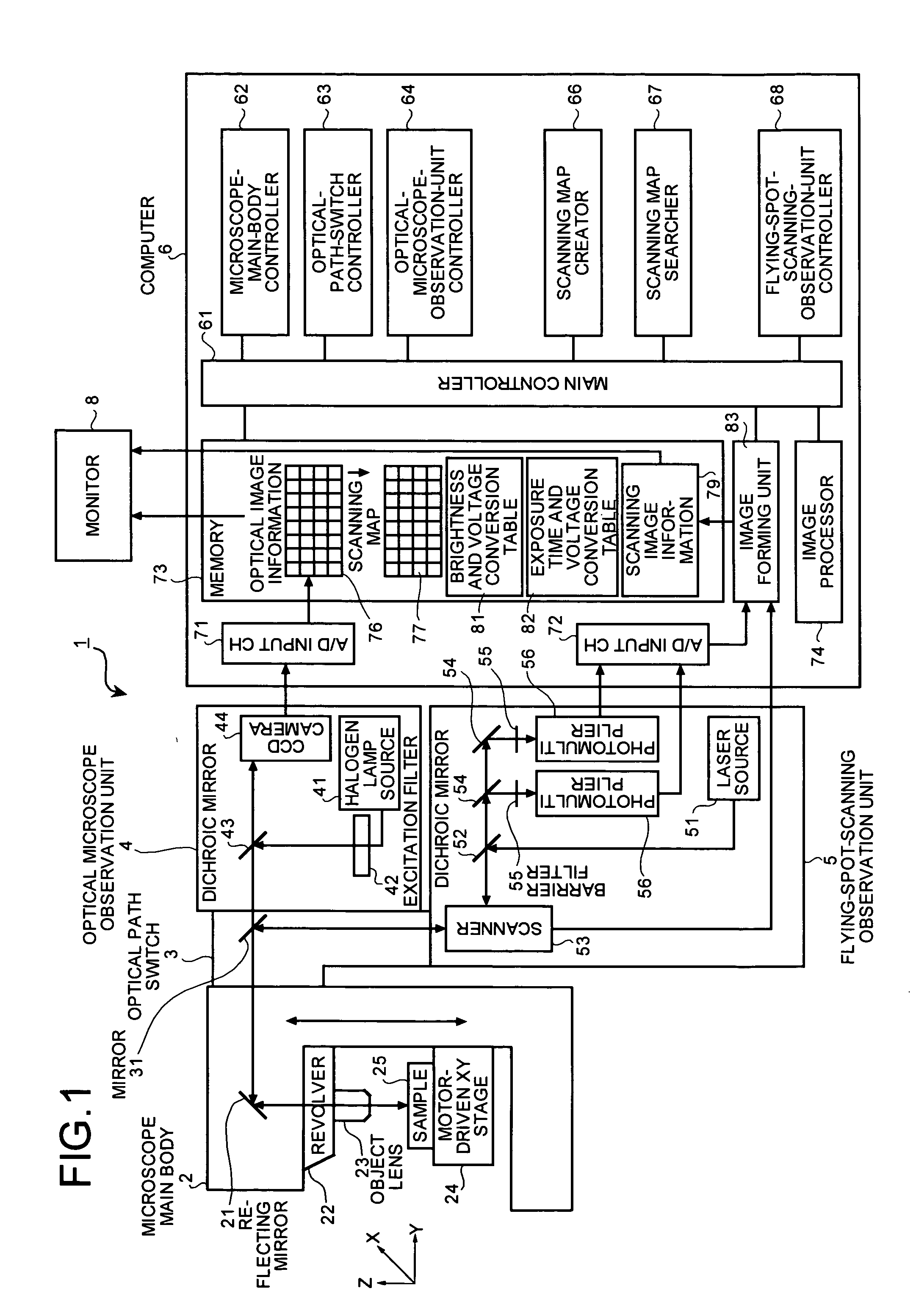
[0029]FIG. 1 is a block diagram that depicts a configuration of a scanning microscope system according to the first embodiment. In the scanning microscope system 1, an optical path in a microscope main body 2 is connected to an optical microscope observation unit 4 and a flying spot scanning observation unit 5 through an optical path switch 3, and the microscope main body 2, the optical microscope observation unit 4, and the flying spot scanning observation unit 5 are connected to a computer 6 including a monitor 8 in order to control the system.
[0030] The computer 6 includes a main controller 61, a microscope-main-body controller 62 an optical-path-switch controller 63, an optical-microscop...
second embodiment
[0074] A second embodiment has a configuration in which a disk in which a plurality of pinholes or a plurality of slits are formed is inserted into a confocal position on an optical path in an optical microscope observation unit 4, a plurality of confocal images are acquired while moving a focus in the Z direction by rotating the disk, a plurality of acquired confocal images are laminated in the Z direction to form a three-dimensional image, regions in which substances to be observed exist are screened, based on the three-dimensional image, and regions to be inspected with a flying spot scanning observation unit 5 are specified.
[0075]FIG. 9 is a block diagram that depicts a configuration of a scanning microscope system 100 according to the second embodiment of the present invention. In the scanning microscope system 100 shown in FIG. 9, components similar to those in the scanning microscope system 1 according to the first embodiment shown in FIG. 1 are denoted by the same reference ...
third embodiment
[0097] Then, processing that acquires scanning image information 79 excited by each fluorescence when a sample is multiple-stained is explained in the When the sample 25 is multiple-stained, an excitation filter 43 in the optical microscope observation unit 40 is changed according to the fluorescence with which the sample 25 is stained, and the wavelength of the excitation light with which the sample 25 is irradiated is switched to respectively acquire a confocal image 92. The scanning map 77 is created for each piece of acquired confocal image information 92 to laminate it in the Z direction. Thereby, a three-dimensional scanning map 97 like one as shown in FIG. 14A is created for each fluorescence with which the sample 25 is stained.
[0098] For example, when the sample 25 is stained with triple fluorescence excited by three wavelengths of 351 nm, 488 nm, and 543 nm, the wavelength of the excitation filter 43 in the optical microscope observation unit 40 is switched to 351 nm in th...
PUM
| Property | Measurement | Unit |
|---|---|---|
| wavelength | aaaaa | aaaaa |
| wavelength | aaaaa | aaaaa |
| wavelength | aaaaa | aaaaa |
Abstract
Description
Claims
Application Information