Method for designing a mold, method for producing an injection molding, program and injection molding device

Inactive Publication Date: 2005-04-21
SUMITOMO CHEM CO LTD
View PDF5 Cites 27 Cited by
  • Summary
  • Abstract
  • Description
  • Claims
  • Application Information

AI Technical Summary

Benefits of technology

[0024] A further aspect of the present invention is a program for the purpose of obtaining a desired injection molding condition, in the case of implementation of injection molding by use of a mold having a plurality of resin inflow conduits to a cavity, wherein a process that determines a mold design parameter in relation to at least one of the arrangement, the shap

Problems solved by technology

Consequently, it is difficult to control a complexly-shaped weld line where the resin flows from three directions merge.
Also according to the metho

Method used


Image

  • Method for designing a mold, method for producing an injection molding, program and injection molding device
  • Method for designing a mold, method for producing an injection molding, program and injection molding device
  • Method for designing a mold, method for producing an injection molding, program and injection molding device

Examples


first embodiment

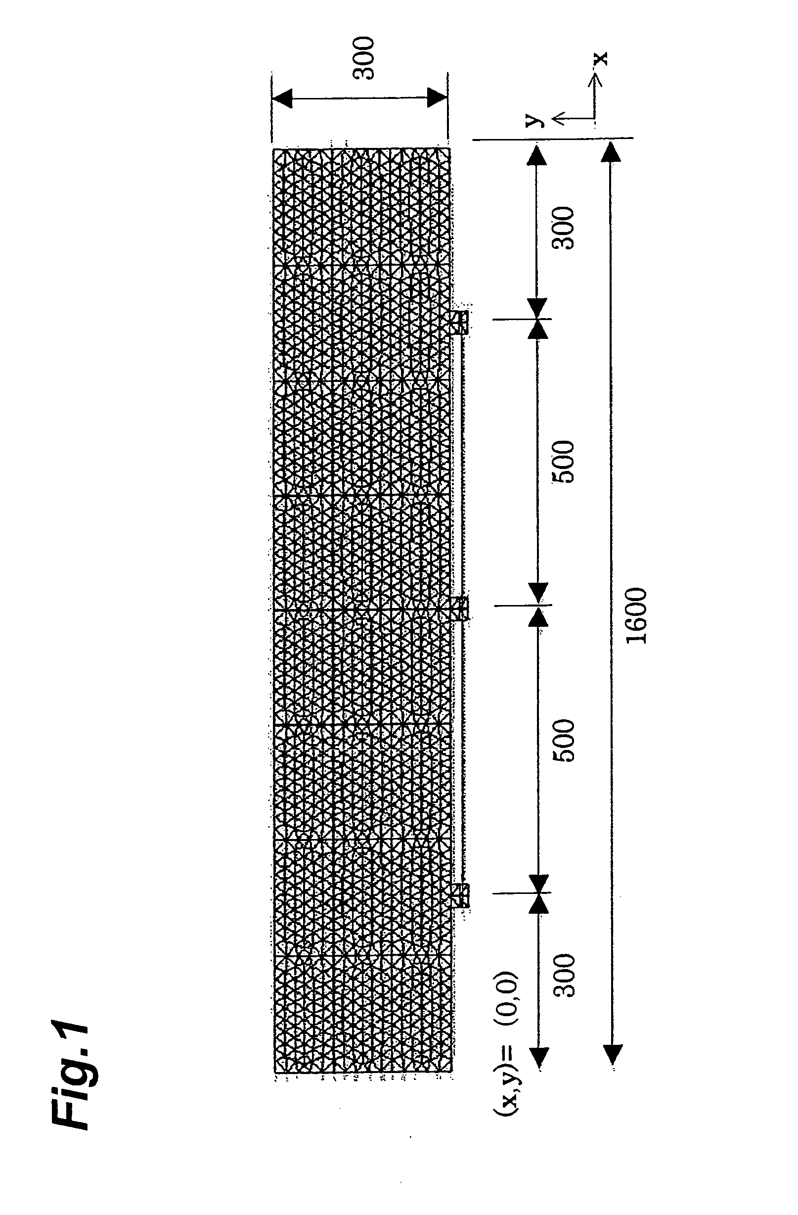
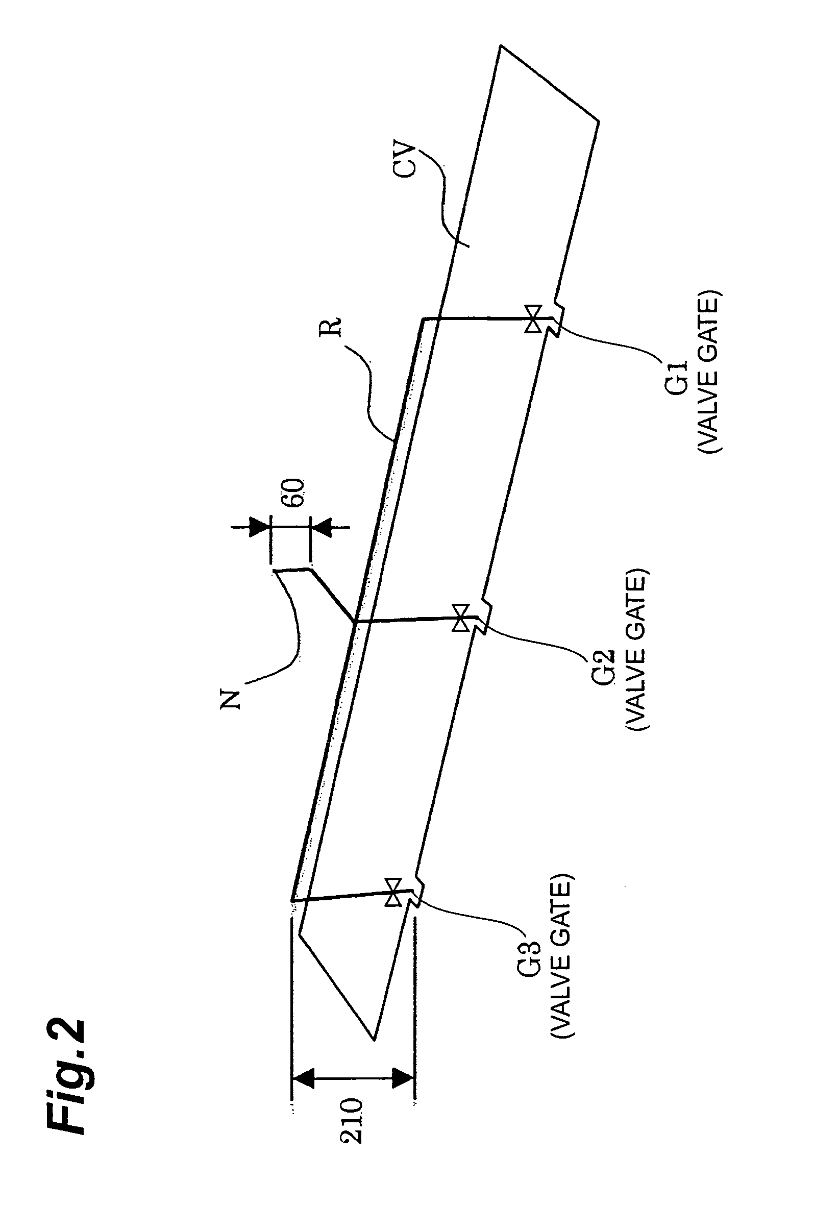
[0043] the present invention will be described in detail below referring to drawings. This embodiment deals with a case of manufacturing a plate-shaped member extending in one direction (a length-to-width ratio=3 / 16), as shown in FIG. 1, by injection molding using predetermined resin material. As depicted in FIG. 2, a cavity CV has three gates (G1, G2, and G3) at the center, the right, and the left on one side of the plate. According to the present invention, the number of gates is required only to be two or more and may be adequately determined depending on the shape and dimensions of a resin product.

[0044] The present invention has such a configuration that at least one gate is a valve gate which can be opened and closed by the valve movement, and injection molding is conducted so that weld lines are formed at desired positions through the adjustment of the valve gate opening degree. This embodiment is configured in such a way that all the three gates are valve gates as shown in F...

second embodiment

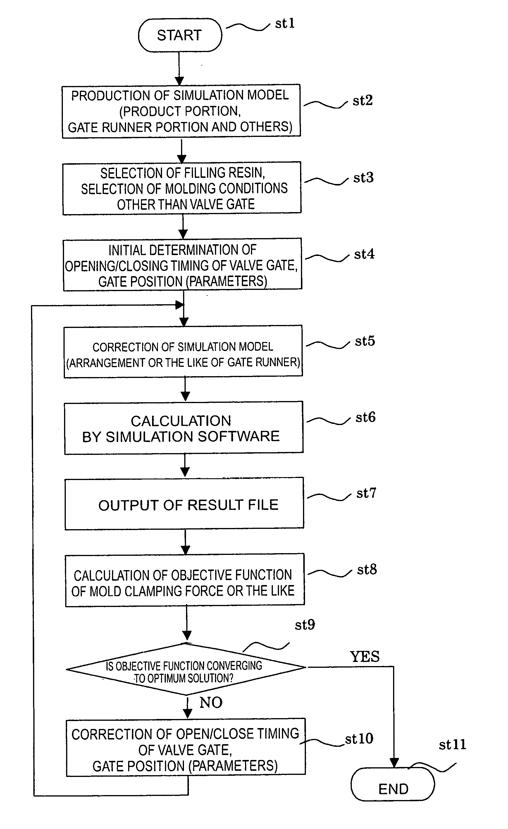
[0046] In this embodiment, a mold design parameter for obtaining the preferred injection condition related to at least one of the arrangement, the shapes and the sizes of the resin inflow conduits is determined by the combination of a numerical analysis method for calculating an injection molding process and a computer-aided optimization method, and a process parameter to set a resin inflow in the molding process, are determined together therewith. In the case of using no valve gate as the second embodiment described later, only the mold design parameter may be determined.

[0047] Regarding the numerical analysis method to calculate the injection molding process, the method in which the behavior of resin is analyzed based on the finite element method using calculation equations on the basis of the relationship working between elements during molding, has been brought into practical application in recent years. The embodiment adopts Moldflow Plastics Insight 2.0 rev1 (trade name, produ...


PUM

PropertyMeasurementUnit
Forceaaaaaaaaaa
Sizeaaaaaaaaaa

Abstract

An object of the present invention is to provide a method for designing a mold and a method for producing an injection molding in which a mold clamping force or weld line occurrence can be more accurately controlled in the case of injection molding of a resin product. In the case where an injection molding is carried out using a mold having a plurality of resin inflow conduits G1, G2, G3 to a cavity CV, a mold design parameter in relation to at least one of the arrangement, the shapes and the sizes of the resin inflow conduits is determined by the combination of a numerical analysis method for calculating an injection molding process and a computer-aided optimization method, for the purpose of obtaining a preferable injection molding condition. Thereby the mold design parameter can be promptly and accurately calculated without repetition of trial and error manually.

Description

BACKGROUND OF THE INVENTION [0001] 1. Field of the Invention [0002] The present invention relates to a method for designing a mold in the case of injection molding of resin, a program for making a computer carry out the process of injection molding, a method for producing an injection molding that produces the injection molding using the mold, and an injection molding device. [0003] 2. Related Background Art [0004] In injection molding, a plurality of gates are required depending on the size and the shape of a is product. In this case, as described below, there have been made proposals of improvement in molding process aspect or in product quality aspect, such as reduction in necessary mold clamping force and weld line position control, through controlling the state of flow of the molten material inflow through the gates. [0005] For example, Japanese Patent Laid-open Gazette No. 2002-355866, page 2 discloses, in the case where the product shape extends in a longitudinal direction, t...

Claims


Application Information

Patent Timeline
IPC IPC(8): B29C33/38B29C45/76G06F17/50
CPCB29C33/3835G06F2217/41B29C2945/76505B29C2945/76531B29C2945/76548B29C2945/76551B29C2945/76568B29C2945/76648B29C2945/76702B29C2945/76859B29C2945/76866B29C2945/76869B29C2945/76872G06F17/5018B29C45/7693G06F30/23G06F2113/22
Inventor NAGAOKA, SHINICHIHIROTA, TOMOOTOGAWA, YOSHIAKI
Owner SUMITOMO CHEM CO LTD
Why Eureka
Try Eureka