White light emitting diode

a light-emitting diode and white light-emitting technology, which is applied in the direction of discharge tubes, luminescent screens, instruments, etc., can solve the problems of unnatural color of emitted light from led, poor color rendering property of led, and small color range of led

Inactive Publication Date: 2005-04-21
CITIZEN ELECTRONICS CO LTD
View PDF4 Cites 137 Cited by
  • Summary
  • Abstract
  • Description
  • Claims
  • Application Information

AI Technical Summary

Problems solved by technology

However, in the LED comprising a combination of the LED elements, because each LED element, that is to say, each of the R-LED element, the G-LED element and the B-LED element has an excellent monochromatic peak emission wavelength, if it is used for a light emitting source of white color system, there is a problem that the color range of the LED is small and the color of emitted light from the LED is unnatural; in other words, the LED has a poor color rendering property.
Therefore, the color rendering property of the LED is poor, and Ra becomes about 12 (in case of the natural light, Ra=100).
Meanwhile, when the color rendering property of the LED is poor, it is unsuitable to use the LED as an illumination source in a read-out device such as a scanner device and a photocopier for detecting reflected light on an object or other devices.
However, there is still a problem in the conventional white LED including the blue LED element and the fluorescent material of the YAG or the like as follows.
Therefore, this results in lack of repeatability in

Method used


Image

  • White light emitting diode
  • White light emitting diode
  • White light emitting diode

Examples


first embodiment

[0045] A white LED according to the present invention is first explained.

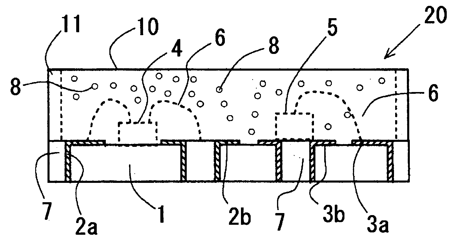
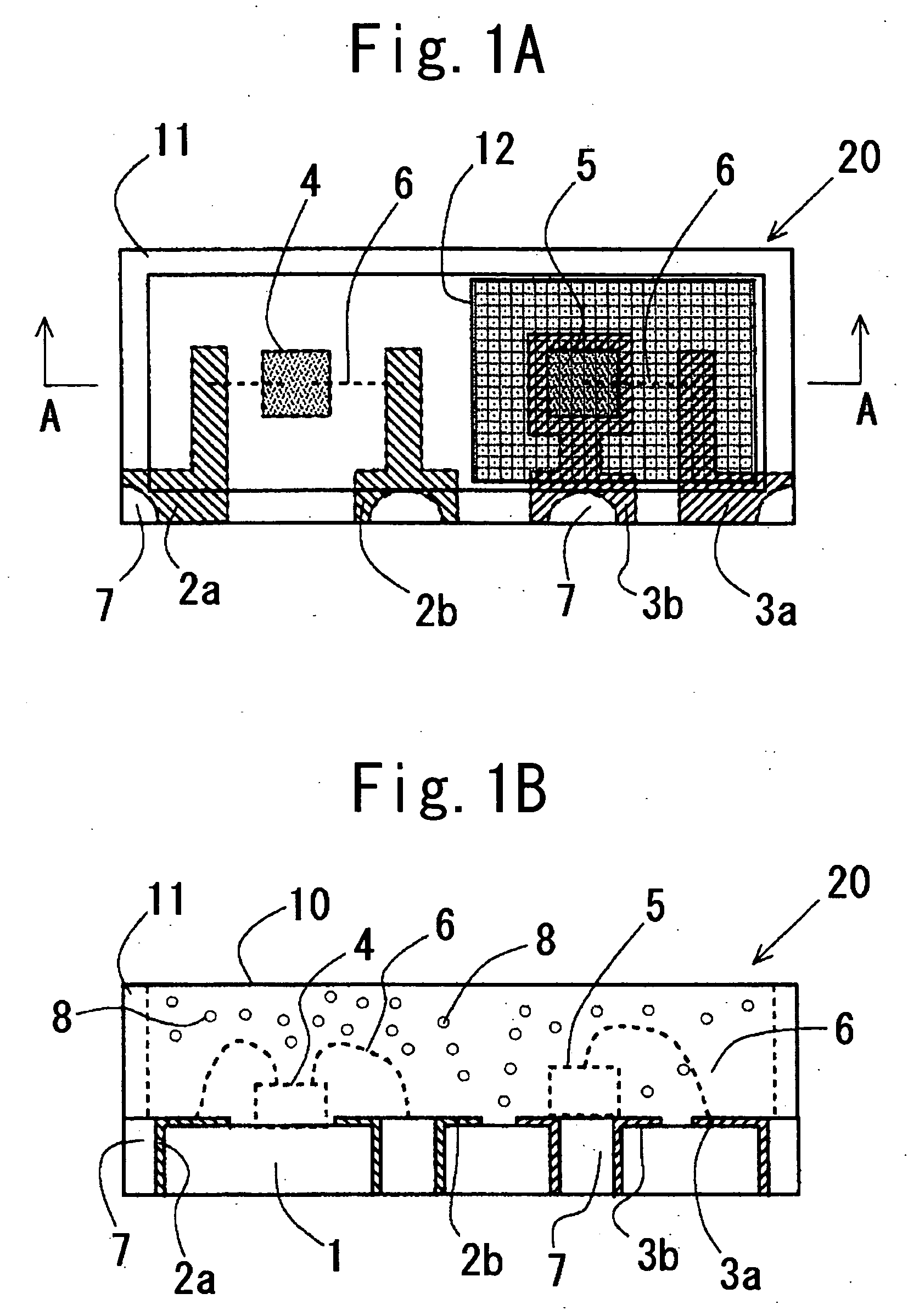
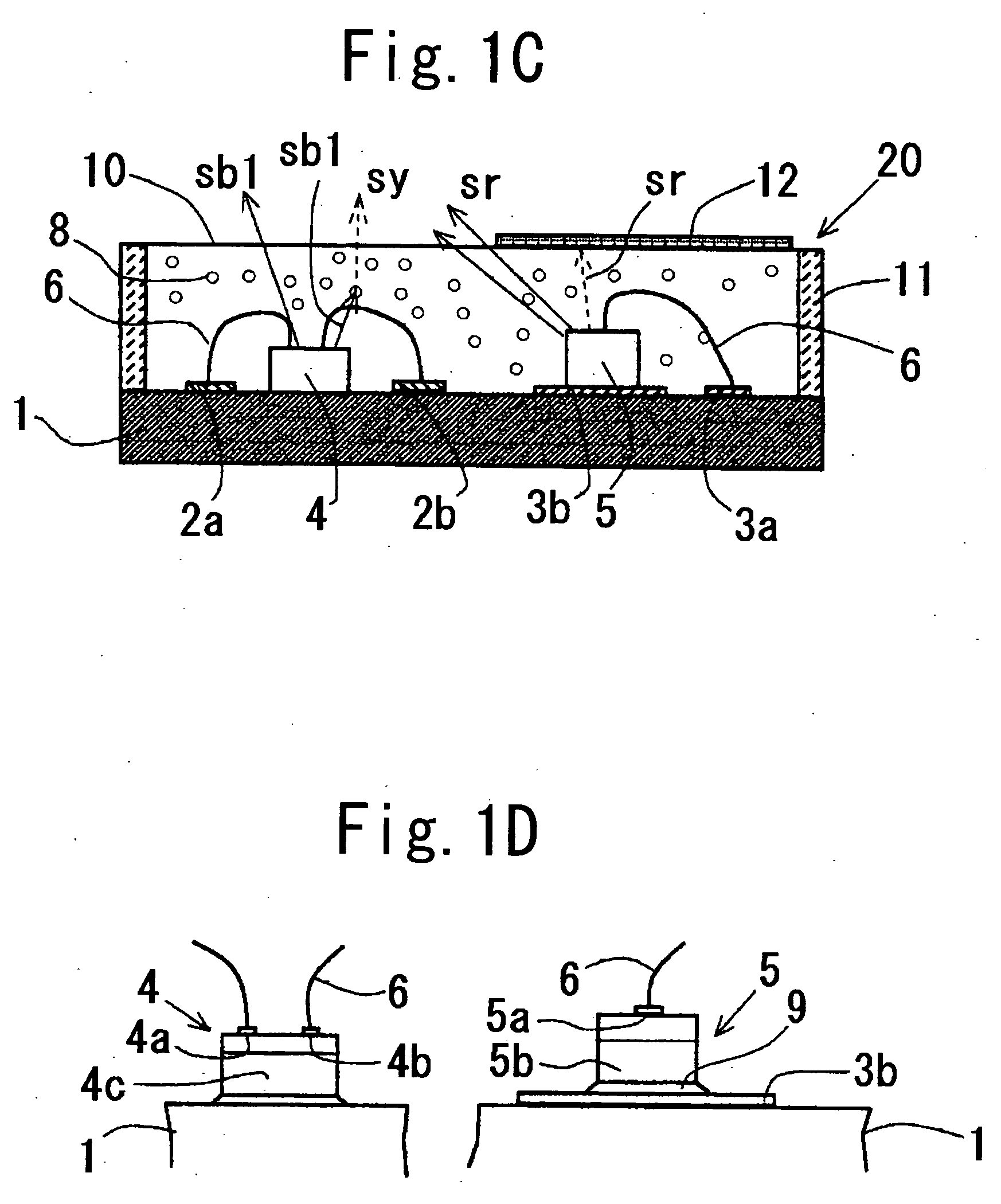
[0046]FIGS. 1A to 1D illustrate the structure of the white LED 20 in the first embodiment. The white LED 20 comprises a surface-mounted LED, which belongs to a fluorescent material-color mixing type LED with red complementary effect, which is targeted to emit white light. In FIGS. 1A to 1D, reference numeral 1 is an insulative board having a generally rectangular shape and made of epoxy resin and so on including glass fibers, 2a and 2b a pair of connecting electrodes for a blue LED element 4, 3a and 3b a pair of connecting electrodes for a red LED element 5, four through-holes 7 formed on a side surface of the board 1, for example.

[0047] The connecting electrodes 2a and 2b for the blue LED element 4 and the connecting electrodes 3a and 3b for the red LED element 5 are patterned on an upper surface of the board 1 and extend to inner surfaces of the through-holes 7 corresponding to the connecting electrodes, res...

second embodiment

[0065] Next, a white LED according to the present invention will be described.

[0066]FIGS. 2A and 2B illustrate the entire structure of the white LED 30 according to the second embodiment of the present invention. In FIG. 2B, 27 is a white light emitting body in which a red LED element 5, a first long wavelength-blue LED element 14a and a second long wavelength-blue LED element 14b, which are mounted on a substrate 21, are sealed by a sealing resinous member 19 containing a fluorescent material, and 31 a reflecting frame. The white LED element 30 has a structure of attaching the reflecting frame 32 to the substrate 21 of the white light emitting body 31, as shown in FIG. 2A.

[0067] As shown in FIGS. 2B and 3A, opposed side surfaces of the substrate 21 are formed with six through-holes, first blue-connecting electrodes 23a and 23b, second blue-connecting electrodes 24a and 24b, and red-connecting electrodes 25a and 25b are formed on an upper surface of the substrate 21 and are extende...

third embodiment

[0072] Next, a white LED according to the present invention will be explained.

[0073]FIG. 4A to 4C illustrate a structure of the white LED 40 according to the third embodiment of the present invention.

[0074] In FIGS. 4A to 4C, 41 is a substrate, 45 a red LED element, 44a, 44b, 44c and 44d are long wavelength-blue LED elements. An emission intensity from the red LED element 45 is approximately 650 nm, and emission intensities from the long wavelength-blue LED elements 44a, 44b, 44c and 44d are in the range of 470 nm to 490 nm. 55a and 55b are red-connecting electrodes, 54a1 and 54a2 a pair of connecting electrodes corresponding to the long wavelength-blue LED element 44a, 54b1 and 54b2 a pair of connecting electrodes corresponding to the long wavelength-blue LED element 44b, 54c1 and 54c2 a pair of connecting electrodes corresponding to the long wavelength-blue LED element 44c, and 54d1 and 54d2 a pair of connecting electrodes corresponding to the long wavelength-blue LED element 44d...


PUM


Abstract

A white LED (20) for emitting illumination light entirely to exterior, comprising a first LED element (4) and a second LED element (5) which have mutually different emission wavelengths, and a sealing member (10) including a fluorescent material (8) which is excited to emit yellow light (sy) and for sealing at least the first LED element, the first LED element (4) being a long wave length-blue LED element for emitting blue light (sb 1) of a long wave length in which a peak wave length is in the range of 470 nm to 490 nm, the second LED element being a red LED element for emitting red light (sr).

Description

CROSS REFERENCE TO THE RELATED APPLICATION [0001] The application claims the priority benefit of Japanese patent Application No. 2003-358575, filed on Oct. 17, 2003, the entire descriptions of which are incorporated herein by reference. BACKGROUND OF THE INVENTION [0002] 1. Field of the Invention [0003] The present invention relates to a light emitting diode or LED used as a backlight for a liquid crystal display for performing a color display, illumination of a flush for photographing a still or moving picture, the other usual light emitting source for illumination, more specifically to an improvement in a white light emitting diode device (hereinafter, referred to as white LED) capable of emitting white light or light close to the white light. [0004] 2. Description of Related Art [0005] Because an LED chip (hereinafter, referred to as LED element) is a semi-conductor element, it has been known that the LED element has a longer operating life and good driving characteristic, is com...

Claims


Application Information

Patent Timeline
IPC IPC(8): G03B27/72H01L25/075H01L33/50H01L33/60H01L33/62
CPCG03B27/72H01L25/0753H01L33/46H01L33/50H01L2224/48091H01L2224/73265H01L2924/3025H01L2924/00014H01L2924/00
Inventor FUKASAWA, KOICHIOISHI, NODOKA
Owner CITIZEN ELECTRONICS CO LTD
Why Eureka
Try Eureka