Timing signal generation apparatus

Inactive Publication Date: 2005-04-21
SONY CORP
View PDF6 Cites 0 Cited by
  • Summary
  • Abstract
  • Description
  • Claims
  • Application Information

AI Technical Summary

Benefits of technology

[0007] Nowadays, the period of time for the development of solid-state image pick-up devices is becoming substantially shortened and the price thereof is decreasing, while on the other hand, various endeavors for increasing the numbe

Problems solved by technology

Nowadays, the period of time for the development of solid-state image pick-up devices is becoming substantially shortened and the price thereof is decreasing, while on the other hand, various endeavors for increasing the number of pixels and improving the performance of the solid-state image pick-up devices are under way, and when any improved solid-state image pick-up device is realized, generally its driving timing is not interchangeable with the others.
However, according to the aforementioned conventional timing generator,

Method used


Image

  • Timing signal generation apparatus
  • Timing signal generation apparatus
  • Timing signal generation apparatus

Examples


Example

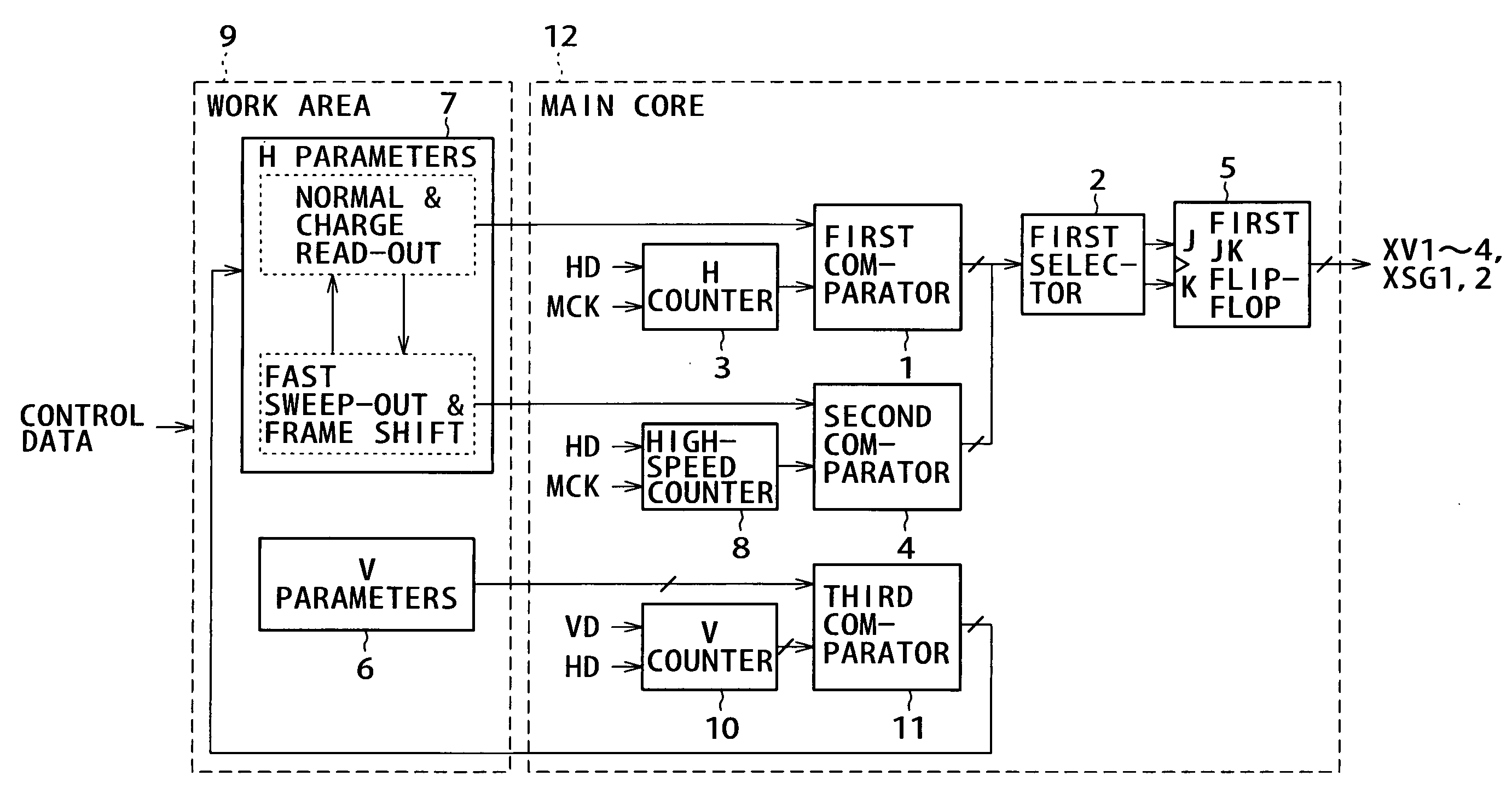
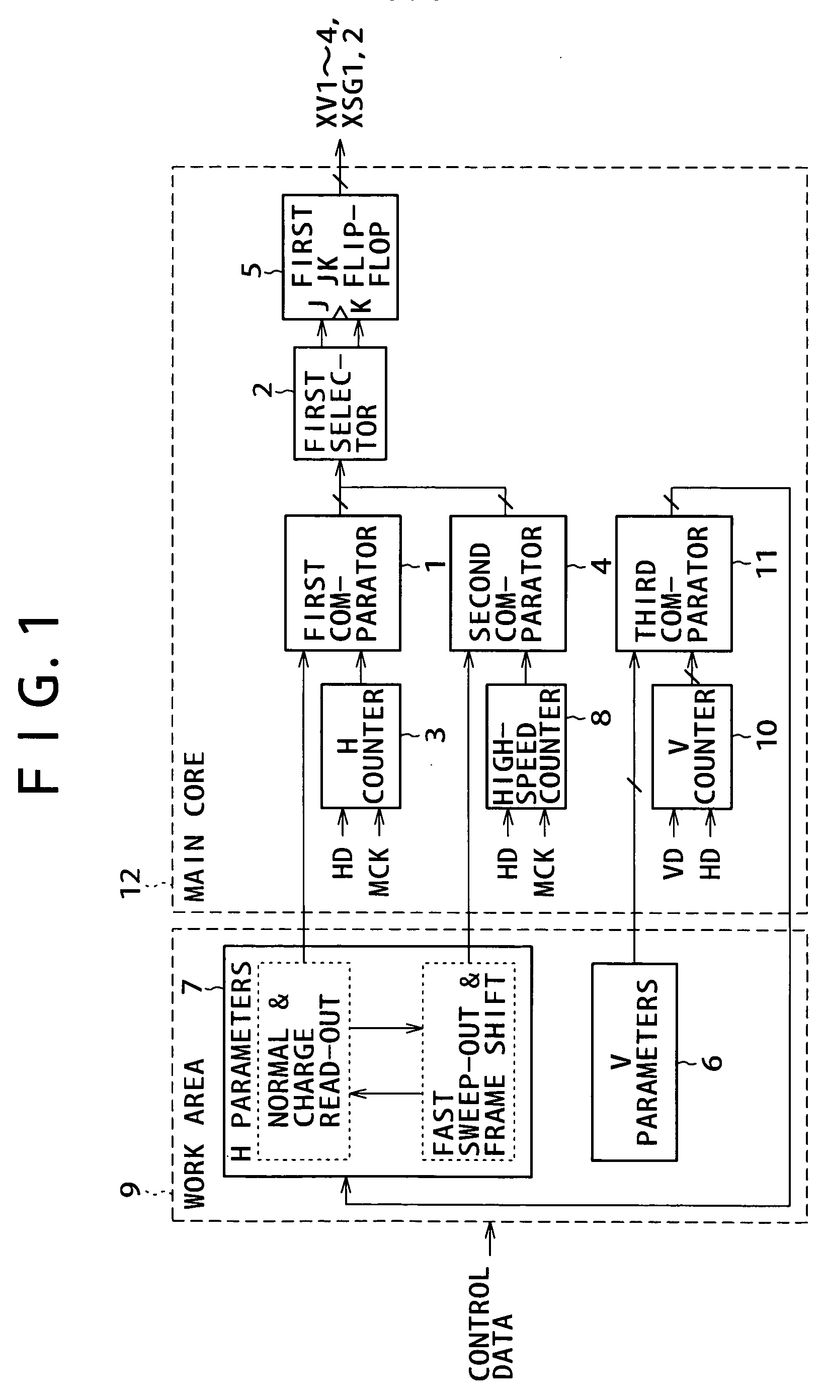
[0016] A preferred embodiment of the present invention will be described in detail by referring to the accompanying drawings in the following. FIG. 1 is a schematic block diagram showing a timing generator which is an example of timing signal generation apparatuses according to a preferred embodiment of the present invention. The timing generator shown here is comprised of a main core 12 which is standardized in a hardware description language level prior to a logic synthesis in its LSI circuit design, and a work area 9 for describing numeric data indicating respective changing points in timing pulses in respective vertical transfer modes such as an ordinal transfer, a high-speed sweep out transfer, a charge read-out transfer and a frame shift transfer timings.

[0017] Here, the work area is comprised of a V parameter 6 and an H parameter 7.

[0018] Further, the main core is comprised of: a V counter 10 which carries out counting triggered by a vertical synchronizing signal VD and als...


PUM


Abstract

A timing generator capable of improving design efficiency by facilitating adaptation to change in design. The timing generator has work area 9 which outputs parameters in response to control data, and main core 12 to which the parameters are inputted. In the work area, V and H parameters are described. The main core consists of third comparator 11 for comparing a count value of V counter 10 with V parameter and outputting a first control pulse, first comparator 1 for comparing a count value of H counter 3 with H parameter and outputting a second control pulse, second comparator 4 for comparing a count value of high speed counter 8 with H parameter and outputting a third control pulse, first selector 2 for selecting the second control data or the third control data, and first JK flip flop 5 for generating a timing signal from output of the first selector.

Description

CROSS REFERENCE TO RELATED APPLICATION [0001] This application claims priority from Japanese Priority Application No. 2003-354509, filed on Oct. 15, 2003 with the Japanese Patent Office, the entire content of which is hereby incorporated by reference. BACKGROUND OF THE INVENTION [0002] 1. Field of the Invention [0003] The present invention relates to a timing signal generation apparatus and, in particular, it relates to a timing signal generation apparatus for supplying a timing signal to a solid-state image pick-up device in accordance with set-up information thereof. [0004] 2. Description of Related Art [0005] A solid-state image pick-up device such as a video camera and a digital still camera using a solid-state image pick-up element such as a CCD is generally known. Such a solid-state image pick-up device is provided with a control circuit for systematically controlling respective functions of an image pick-up section, a signal processor section, a record processor section and t...

Claims


Application Information

Patent Timeline
IPC IPC(8): H03L7/06H04N5/06H04N5/073H04N5/335H04N5/376
CPCH04N5/06H04N5/335H04N5/073H04N25/00
Inventor ITO, MASANOBUTSUTAMURA, KOICHI
Owner SONY CORP
Why Eureka
Try Eureka