
Keyboard with keys for moving cursor

Inactive Publication Date: 2005-04-21
CUFER ASSET LTD LLC
View PDF63 Cites 9 Cited by
  • Summary
  • Abstract
  • Description
  • Claims
  • Application Information

AI Technical Summary

Benefits of technology

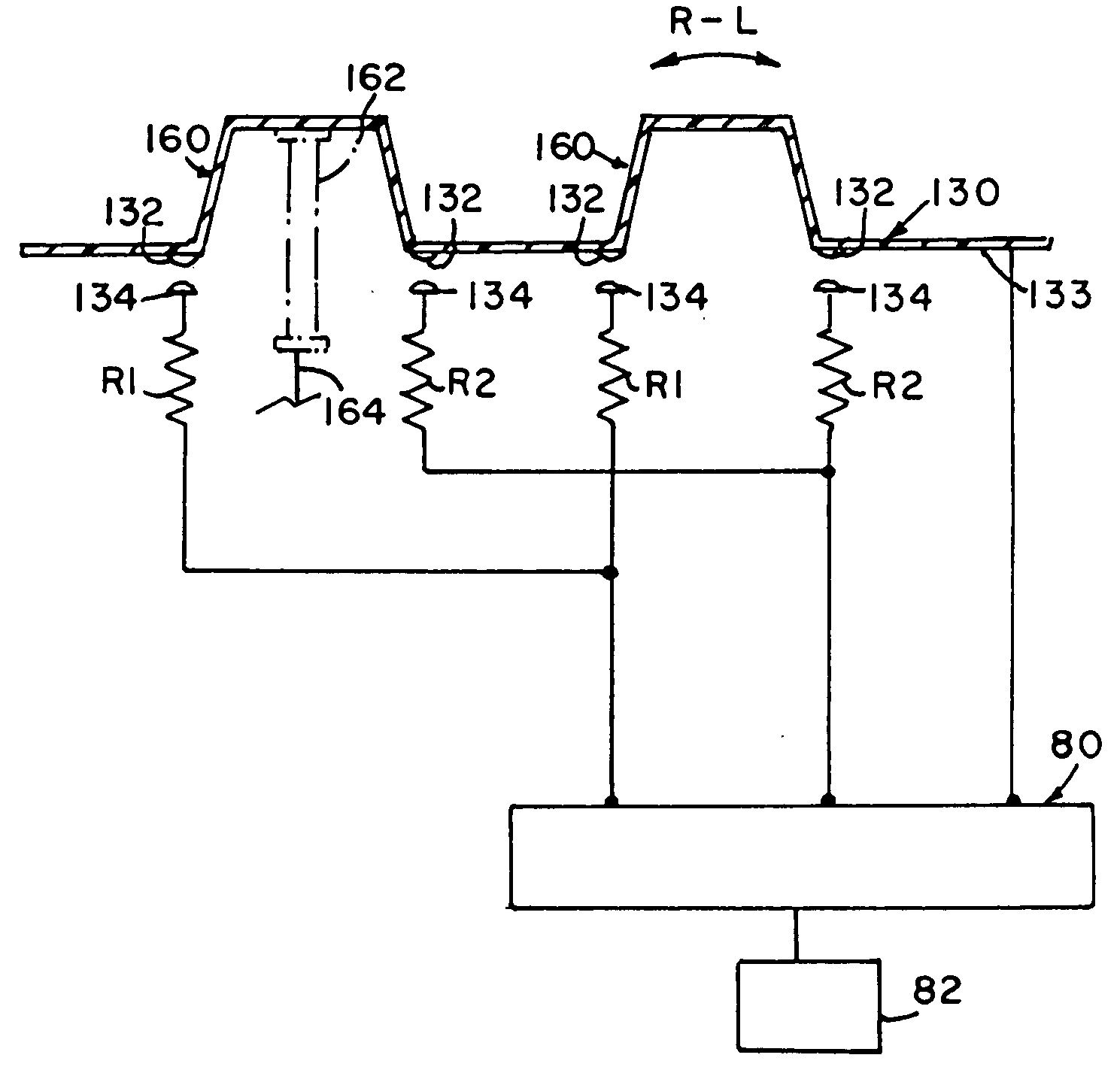
[0011] The invention, in a further embodiment, comprise a signal generator for sending information to a computer monitor to effect proportional directional movement of a pointer or cursor on that monitor, comprising a plurality of the regular alpha-numeric depressable keys on the signal generator for the sending of electrical signals to the monitor through an electrical circuit, and a further electrical circuit arranged between each of said plurality of depressable keys and the signal generator, to effect motion in a cursor on the monitor, when the plurality of keys are depressed somewhat sideways or skewedly. The further electrical circuit in one embodiment, comprises a multiplicity of electrical components spaced adjacent the periphery of each of the plurality of depressable keys, each of the spaced components connected in parallel to correspondingly positioned components spaced about the other of the depressable keys, and connected to a processing unit for input to said monitor. The electrical components may comprise resistors which are variable in nature such as potentiometers, strain gages, or conductors in communication with the compressable foam (variable conductivity depending on the amount of conductors therein, and the amount of compression applied thereto), comprising part of a secondary contact point to receive signals when any of the keys are depressed or moved in a skewed or sideways direction. The signal generator may have an upper surface comprised of a layer of flexible plastic material, and the plurality of depressable keys may also formed of that flexible plastic material. A plurality of primary contact points are disposed on the lower surface of the layer of flexible material juxtaposed with respect to the secondary contact points to permit electrical communication therebetween when any of the plurality of keys are moved in a skewed manner, or pressed with an increased force to create a greater conductivity to get such cursor to move faster.
[0012] The invention further comprises a method of generating an electrical signal in order to effect proportional movement of a cursor on a computor monitor, comprising the steps of arranging a plurality of movable (depressable) keys on a keyboard so that when any of the keys (preferrably standard alpha/numeric keys) are moved, an electrical signal is sent through a first electrical circuit to a processing unit and to a monitor for display of that signal thereon, and arranging a further electrical circuit in a spaced relationship with respect to the keys, so as to send a further electrical signal to the monitor to move a cursor in a particular direction when a plurality of the keys are moved with a sideways component of motion (skewed manner). The method of generating an electrical signal includes pressing simultaneously, more than one of the plurality of depressable keys in a common skewed direction, to effect movement of the cursor or pointer on the monitor in a corresponding direction. The method of generating an electrical signal also comprises the step of increasing the force/speed of the skewed moving or increasing the number of keys simultaneously pressed in a ske

Problems solved by technology

While their keypads are somewhat “storable”, the problem with that type of terminal is that the operator has a difficult time in hitting the proper key to efficiently do the job.
Current laptop and palmtop devices suffer from the problem of short stroke and compacted dense key layout.
Further difficulties arise when cursor movement is desired.
Accuracy, however, may be lacking with such data entry devices, inasmuch as the exact location of a particular cursor / data entry point may be difficult to discern.
This does not facilitate cursor movement while an operator's hands are on the alpha / numeric keys themselves.

Method used


Image

  • Keyboard with keys for moving cursor
  • Keyboard with keys for moving cursor
  • Keyboard with keys for moving cursor

Examples


Embodiment Construction

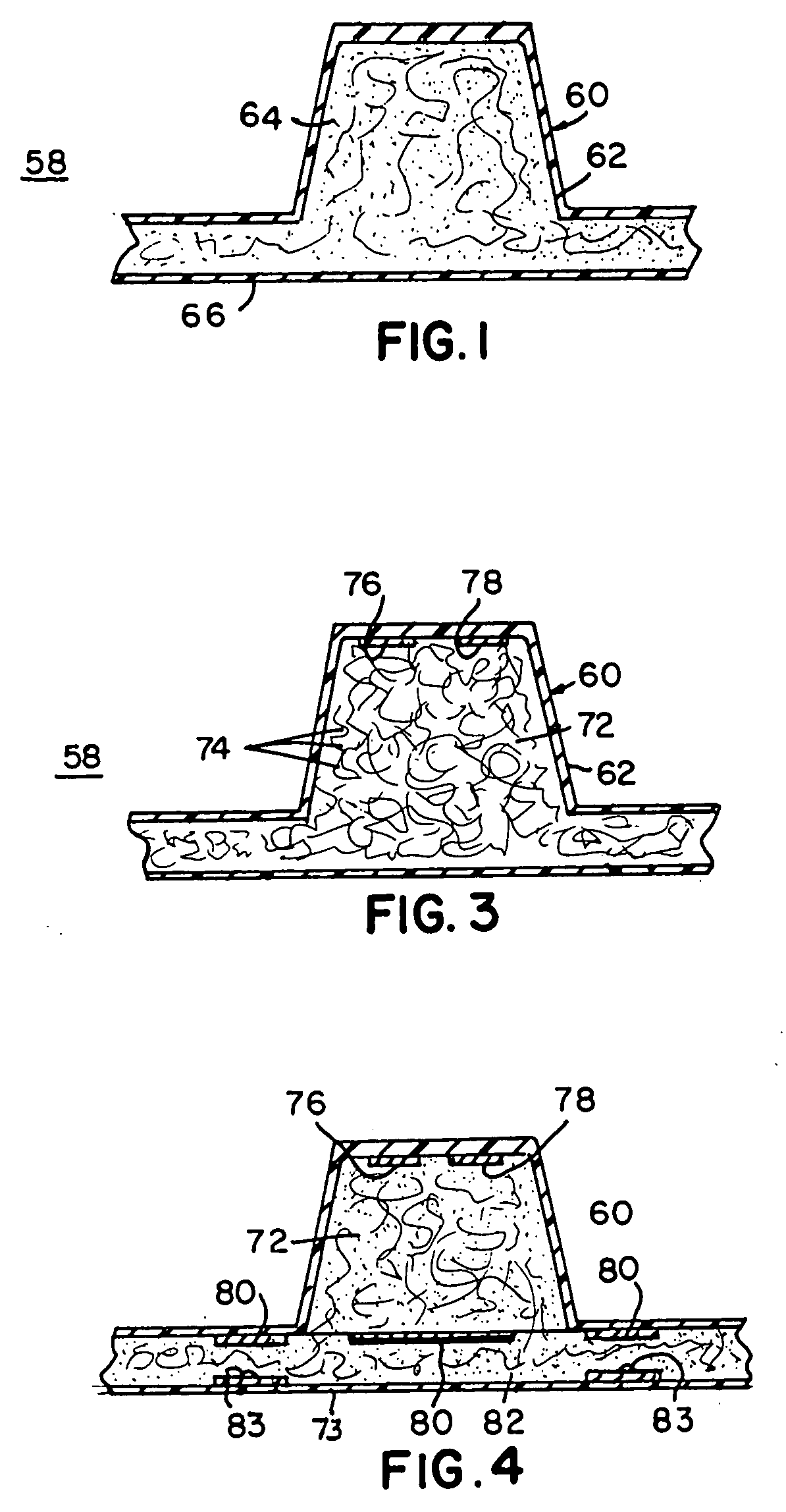
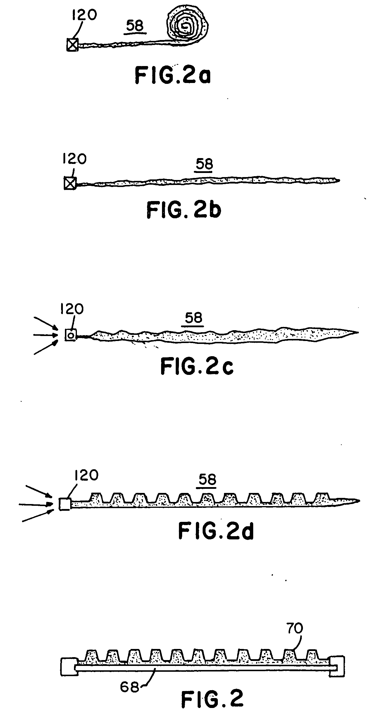
[0027] The present invention relates to an expandable signal generator apparatus 58, as shown in a partial side-elevational view, in FIG. 1, wherein an expandable key 60 has a pre-molded upper layer 62 in a desired key configuration, having an enclosed volume of open or closed cell foam 64. The upper layer 62 of the key 60, being made from a thin layer of plastic material which flexes when pressed by an outside force. The foam 64 is yieldable when pressed, yet has sufficient stiffness to maintain the fullness of the key in the absence of pressure thereon. A lower layer of thin, flexible plastic material 66 of about 10-20 mil thick PVC, or the like, may be disposed across the bottom of the key 60, as shown in FIG. 1. The key may be one of a plurality of such keys on a signal generator 70, which may be, in one embodiment, arrangable on the face of a force pad 68, which pad 68 utilizes “pressure” to generate a signal therewithin, as is shown in a side-elevational view, in FIG. 2.

[0028...


PUM

PropertyMeasurementUnit
Pressureaaaaaaaaaa
Flexibilityaaaaaaaaaa
Speedaaaaaaaaaa

Abstract

The present invention comprises a signal generator for sending an electrical signal from an expandable, flexible layer of material, the signal generator comprising an upper layer of flexible, resilient material and a lower layer of flexible, resilient material which between them define a cavity for enclosing an expandable material such as a cellular foam or gas, whereupon localized distortion of one of the layers of flexible material, effects a signal generation within the structure, which is transmissible through a proper circuit to an outside electrical device. A circuit may be arranged adjacent a plurality of said keys which senses when several of said keys are depressed in a skewed or sideways manner, so as to effect movement of a cursor or pointer on a monitor in communication with a processing unit and said keyboard.

Description

[0001] This application is a Continuation-In-Part application of our co-pending U.S. patent application, Ser. No. 08 / 447,116 filed Aug. 18, 1995, which is a Continuation of our earlier application, Ser. No. 08 / 098,851, now U.S. Pat. No. 5,459,461, both of which are incorporated herein by reference, in their entirety.BACKGROUND OF THE INVENTION [0002] 1. Field of the Invention [0003] This invention relates to keyboards, and more particularly, to signal generating devices which have keys adapted for moving a cursor by themselves in addition to permitting other data input. [0004] 2. Prior Art [0005] Miniaturization of electronic devices such as calculators, computers, telephones, amusement devices, and light electronic equipment has advanced rapidly over the past few years. Data entry devices have become miniaturized as well. The term “chicklet keys” has been used to identify very small tabs or keys utilized on some small devices for data entry into that device. While their keypads are...

Claims


Application Information

Patent Timeline
IPC IPC(8): G06F3/02G06F3/023G06F3/048H01H13/702H01H13/703H01H13/785H01H13/807H03K17/96
CPCG06F3/0202Y10T29/49105G06F3/04892H01H13/702H01H13/703H01H13/785H01H13/807H01H2201/02H01H2201/036H01H2209/006H01H2209/03H01H2209/052H01H2209/074H01H2211/002H01H2215/052H01H2217/034H01H2219/011H01H2221/002H01H2221/012H01H2221/038H01H2221/042H01H2221/084H01H2223/052H01H2225/002H01H2225/018H01H2227/034H01H2229/05H01H2231/01H01H2239/012H01H2239/052H03K17/964G06F3/0221
Inventor CROWLEY, ROBERT J.HALGREN, DONALD N.
Owner CUFER ASSET LTD LLC
Learn More