Prediction model for color separation, calibration and control of printers

a technology of color separation and calibration, applied in the field of printing, can solve the problem that the relative ink thickness value cannot be used to predict, and achieve the effect of high accuracy and convenient printer calibration

Inactive Publication Date: 2005-04-21
ECOLE POLYTECHNIQUE FEDERALE DE LAUSANNE (EPFL)
View PDF15 Cites 49 Cited by
  • Summary
  • Abstract
  • Description
  • Claims
  • Application Information

AI Technical Summary

Benefits of technology

[0011] The present invention facilitates the calibration of printers and the color separation of input images into a set of inks by disclosing methods and systems for populating device-calibration lookup tables. A comprehensive spectral prediction model is used which is capable of predicting at a high accuracy the reflectance spectra of halftone ink patches. The comprehensive spectral prediction model is composed by a first part predicting the reflection spectra as a function of physical (mechanical) surface coverages and by a second part comprising functions mapping nominal surface coverages to effective surface coverages. These mapping functions are calibrated by halftone patch wedges printed alone and by halftone patch wedges printed in superposition with one or several solid inks. The comprehensive spectral prediction model comprises therefore separate mappings for wedges printed alone, for wedges printed in superposition with a second solid ink and possibly for wedges printed in superposition with more than two inks. For the computation of the effective ink coverages of a

Problems solved by technology

Being able to calibrate and control printers and printing presses is a challenge, since until now no comprehensive model exists which is capable of predicting accurately the spectra of polychrome color patches printed on paper.
While offering a better accuracy than other existing models (see H. R. Kang, Applications of color mixing models to electronic printing, Journal of Ele

Method used


Image

  • Prediction model for color separation, calibration and control of printers
  • Prediction model for color separation, calibration and control of printers
  • Prediction model for color separation, calibration and control of printers

Examples


first embodiment

(A)

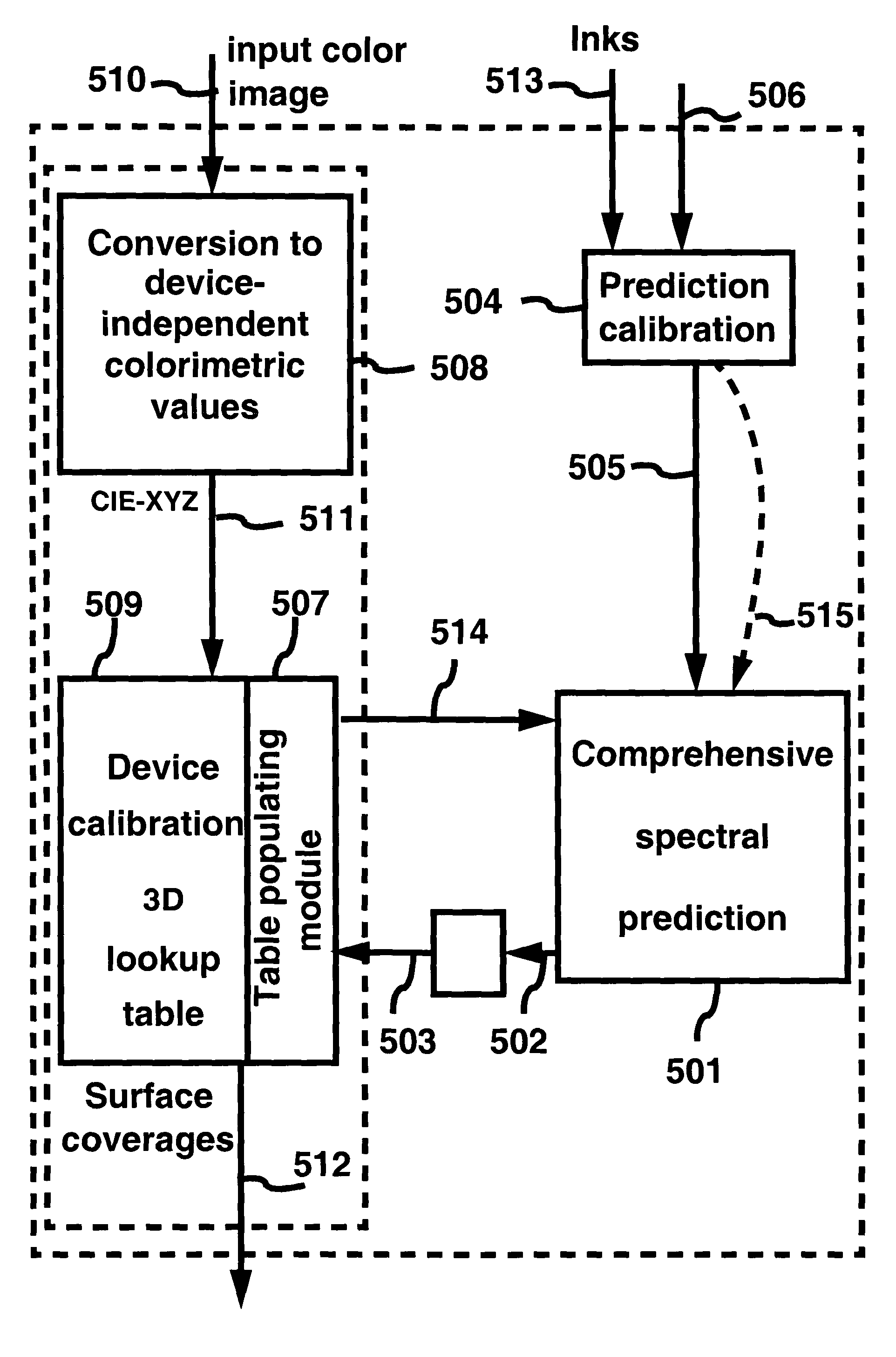
[0134] A system (example shown in FIG. 5) capable of performing the color separation of color images into a set of target inks comprises the following modules.

[0135] 1. A comprehensive spectral color prediction module 501 for predicting reflection spectra 502 (and calorimetric tri-stimulus values 503) of halftone patches printed with nominal surface coverages 514 of a set of inks.

[0136] 2. A comprehensive spectral prediction calibration module 504 for performing the calibration of the comprehensive spectral color prediction module 501. Calibration parameters 505 comprise the internal transmittances of the inks, the internal transmittance of the substrate (paper), the surface coverages of the inks alone and in superposition with one or several other inks, the relative ink thicknesses when two or more inks are superposed and the mapping of given nominal surface coverages to effective surface coverages.

[0137] 3. A device calibration 3D lookup table populating module 507 for fitti...

second embodiment

(B)

[0141] One may also think of a color separation system which, thanks to an extended lookup table, directly maps input image color coordinates 510 to coverages of inks 512. Instead of having entries specified as device-independent colorimetric values, the entries are formed by input image color coordinates sampled at given intervals, e.g. 0%, 10%, . . . , 90%, 100%. This is easily achieved, since a straightforward correspondence exists between input image coordinates (e.g. red, green, blue) and device-independent colorimetric tri-stimulus values (see section 5.8, CRT Displays, Digital Color Imaging Handbook, Ed. G Sharma, CRC Press, 2003, 324-328).

System for the Control of Printers and Printing Presses

[0142] The disclosed system (FIG. 6) for the control of printers (or printing presses) comprises the printer 600, printed pages 601, an image acquisition device 602, an image acquisition & conversion module 603, the printer control system 605, the comprehensive spectral prediction ...


PUM


Abstract

The present invention facilitates the calibration of printers and the color separation of input images into a set of inks by disclosing methods and systems for populating device-calibration lookup tables. The disclosed methods and systems rely on a comprehensive spectral prediction model which is capable of predicting at a high accuracy the reflectance spectra of halftone ink patches. The comprehensive spectral prediction model is composed of a first part predicting the reflection spectra as a function of physical (mechanical) surface coverages and of a second part comprising functions mapping nominal surface coverages to effective surface coverages. These mapping functions are calibrated by halftone patch wedges printed alone and by half-tone patch wedges printed in superposition with one or several solid inks. The part of the comprehensive spectral prediction model predicting the reflection spectra relies on a weighted average between one component behaving according to the Clapper-Yule model and another component behaving as the spectral Neugebauer model, extended to include multiple internal reflections at the paper-air boundary. The disclosed methods and systems can perform the color separation as well as the calibration of printers printing with standard cyan, magenta, and yellow inks as well as with inks comprising standard and non-standard inks such as Pantone inks (custom inks). They are also used for performing precise undercolour removal in order to carry out the color separation of images into cyan, magenta, yellow and black inks. They can further be used to carry out the color separation of images into cyan, magenta, yellow, black, light cyan and light magenta inks. In addition, the disclosed methods and systems can be used for printer control, i.e. to control printer actuation parameters in different types of printers e.g. liquid ink professional printers (offset, gravure, letterpress), electrophotographic printers, ink-jet printers, thermal transfer printers and in dye-sublimation printers.

Description

BACKGROUND OF THE INVENTION [0001] The present invention relates generally to the field of printing and specifically to color separation, calibration and control of printer actuation parameters. It discloses a new comprehensive model for predicting the color of patches printed with standard and / or non-standard inks. It represents an improvement over an initial model (see U.S. patent application Ser. No. 10 / 440,355, “Reproduction of Security Documents and Color Images with Metallic Inks, filed 19th of Jun. 2003, inventors R. D. Hersch, P. Emmel, F. Collaud, and the paper “Reproducing Color Images With Embedded Metallic Patterns” by R. D. Hersch, F. Collaud, P. Emmel, Siggraph 2003 Annual Conference Proceedings, ACM Trans. of Graphics, Vol 22, No. 3, to be published 27th of Jul. 2003), which is used in the context of printing with metallic inks. [0002] Being able to calibrate and control printers and printing presses is a challenge, since until now no comprehensive model exists which ...

Claims


Application Information

Patent Timeline
IPC IPC(8): H04N1/60
CPCG06K2215/0094H04N1/6025H04N1/6097H04N1/6033H04N1/603
Inventor HERSCH, ROGER DAVIDEMMEL, PATRICKCOLLAUD, FABIEN
Owner ECOLE POLYTECHNIQUE FEDERALE DE LAUSANNE (EPFL)
Why Eureka
Try Eureka