High Brightness optical device

a high-brightness, optical display technology, applied in optics, instruments, optical light guides, etc., can solve the problems of inconvenient installation, unsafe use, and several significant drawbacks of state-of-the-art huds, and achieve the effect of improving the brightness of an optical display

Active Publication Date: 2005-04-21
LUMUS LTD
View PDF38 Cites 33 Cited by
  • Summary
  • Abstract
  • Description
  • Claims
  • Application Information

AI Technical Summary

Benefits of technology

[0013] The invention further provides a method for improving the brightness of an optical display, comprising providing an optical display system including a display sourc

Problems solved by technology

State-of-the-art HUDs, however, suffer from several significant drawbacks.
As a result, the present HUD systems usually require complicated high brightness display sources which are necessarily bulky, large, and require considerable installation space, which makes it inconvenie

Method used


Image

  • High Brightness optical device
  • High Brightness optical device
  • High Brightness optical device

Examples


Embodiment Construction

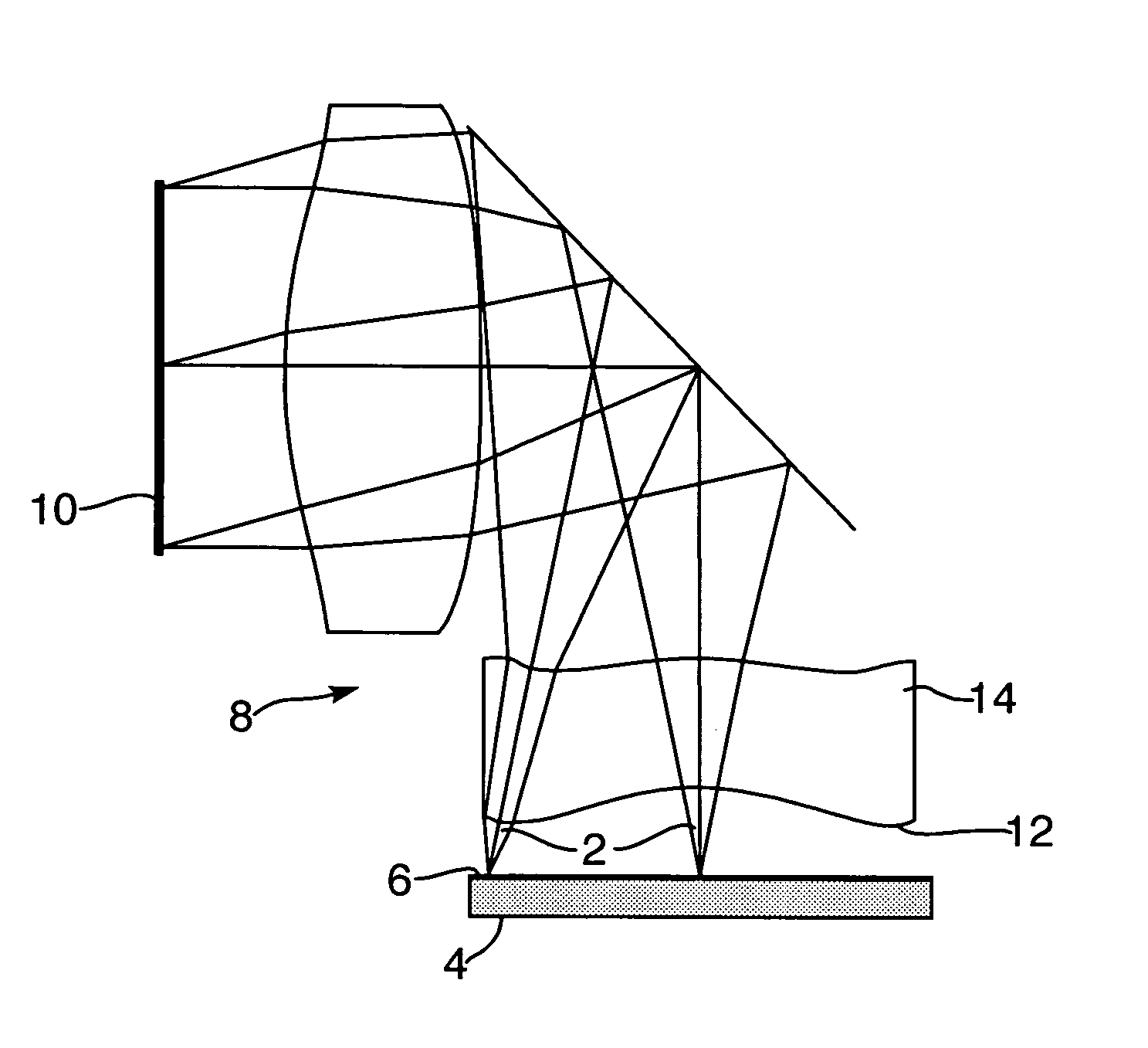
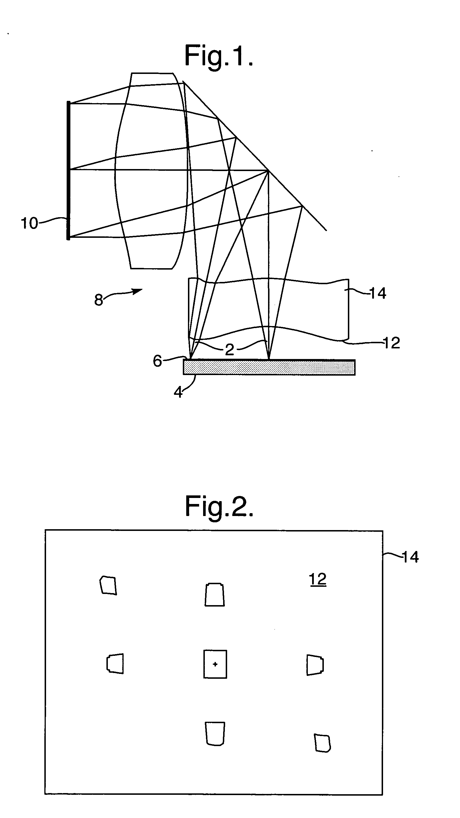
[0024]FIG. 1 illustrates an optical display system, wherein light waves 2 emerging from a display source 4 are diffused by a light diffuser 6, that can be an integral part of the display source, such that each light wave which is emerging from a single point in the display source is diverged into a finite solid angle. Usually, a Lambertian light diffusing mechanism is preferred, that is, a diffuser wherein the brightness is constant regardless of the angle from which it is viewed. The light waves are then imaged by an imaging module 8 and illuminate an output aperture 10 of the optical system. For direct view optical systems, this output aperture can be defined as a head-motion-box or an eye-motion-box for a biocular or a monocular respectively, that is, the location where the viewer can see the entire image simultaneously. Alternatively, for see-through optical systems, where the image is projected into the viewer's eye(s) through an optical combiner, the output aperture is defined...


PUM


Abstract

There is provided an optical device, comprising a display source; a light-diffuser; an imaging optical module, and an output aperture from the optical device characterized in that the light diffuser is an angular, non-uniform diffuser of light for increasing a portion of light emerging from the display source that passes through the output aperture. A method for improving the brightness of an optical display is also provided.

Description

FIELD OF THE INVENTION [0001] The present invention relates to an optical display system and method, and particularly to a display system and method for see-through display applications. [0002] The invention can be implemented to advantage in a large number of personal imaging applications, such as, for example, head-mounted displays (HMDs) and head-up displays (HUDs), hand-held displays, as well as binoculars, monoculars and bioculars. In addition, the same arrangement can be utilized for image projection systems such as front projectors for conference rooms and rear projection TV screens. BACKGROUND OF THE INVENTION [0003] One of the important applications for compact optical elements is in HMDs wherein an optical module serves both as an imaging lens and a combiner, in which a two-dimensional display is imaged to infinity and reflected into the eye of an observer. The image to be displayed is obtained directly from either a spatial light modulator (SLM) such as a cathode ray tube...

Claims


Application Information

Patent Timeline
IPC IPC(8): G02B5/02G02B6/00G02B27/00G02B27/01
CPCG02B5/02G02B5/0252G02B5/0257G02B5/0284G02B2027/0118G02B13/22G02B27/0101G02B27/0172G02B6/00
Inventor AMITAI, YAAKOVGELBERG, JONATHAN
Owner LUMUS LTD
Why Eureka
Try Eureka