Multi-energy x-ray source

a multi-energy x-ray source and imaging system technology, applied in tomography, instruments, diagnostic recording/measuring, etc., can solve the problems of inability to substantially reduce the death toll, disorganized proliferation, leakage and pooling of blood around the tumors,

Active Publication Date: 2005-04-21
VARIAN MEDICAL SYSTEMS
View PDF46 Cites 158 Cited by
  • Summary
  • Abstract
  • Description
  • Claims
  • Application Information

AI Technical Summary

Benefits of technology

[0009] In accordance with another embodiment of the invention, a system for generating CT image data using radiation at a plurality of levels is provided. The system includes a gantry, a x-ray source assembly secured to the gantry, and a detector assembly. By means of non-limiting examples, the x-ray source assembly can include a plurality of voltage supplies, a plurality of target materials (anodes), and/or a plurality of filters, thereby allowing the x-ray source assembly to deliver radiation having different characteri

Problems solved by technology

The death toll cannot be substantially reduced because current screening and diagnostic techniques do not detect all cancers at an early enough stage to effectuate a treatment cure.
Vessels that grow around the tumors proliferate in a disorganized manner and they may leak and pool blood around the tumors.
However, the contrast resolution of mammography is usually limited, and malignancies in tissues that are below 5 millimeters in cross-sectional dimension ma

Method used


Image

  • Multi-energy x-ray source
  • Multi-energy x-ray source
  • Multi-energy x-ray source

Examples


Embodiment Construction

[0023] Various embodiments of the present invention are described hereinafter with reference to the figures. It should be noted that the figures are not drawn to scale and elements of similar structures or functions are represented by like reference numerals throughout the figures. It should also be noted that the figures are only intended to facilitate the description of specific embodiments of the invention. They are not intended as an exhaustive description of the invention or as a limitation on the scope of the invention. In addition, an aspect or a feature described in conjunction with a particular embodiment of the present invention is not necessarily limited to that embodiment and can be practiced in any other embodiments of the present invention.

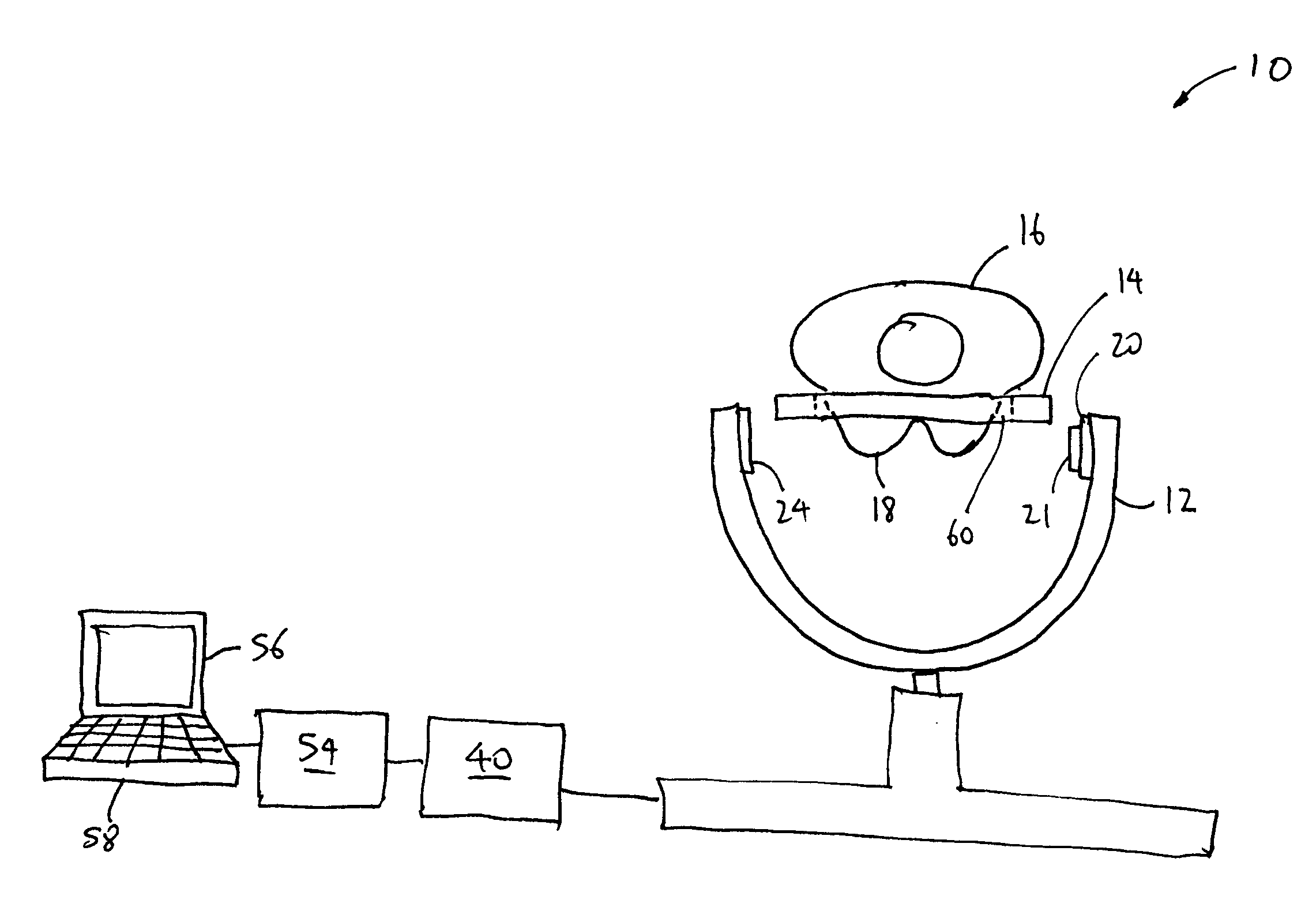
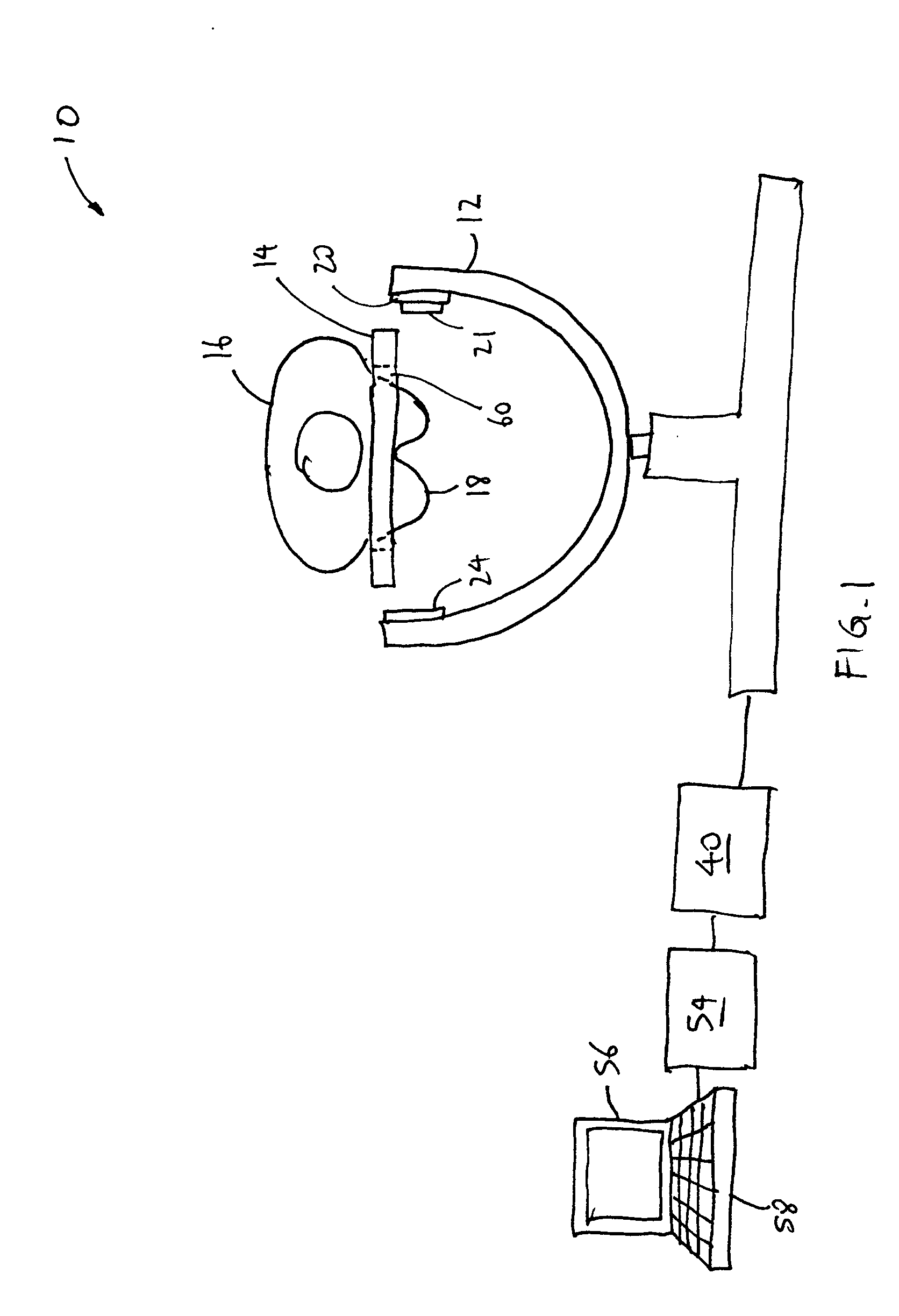
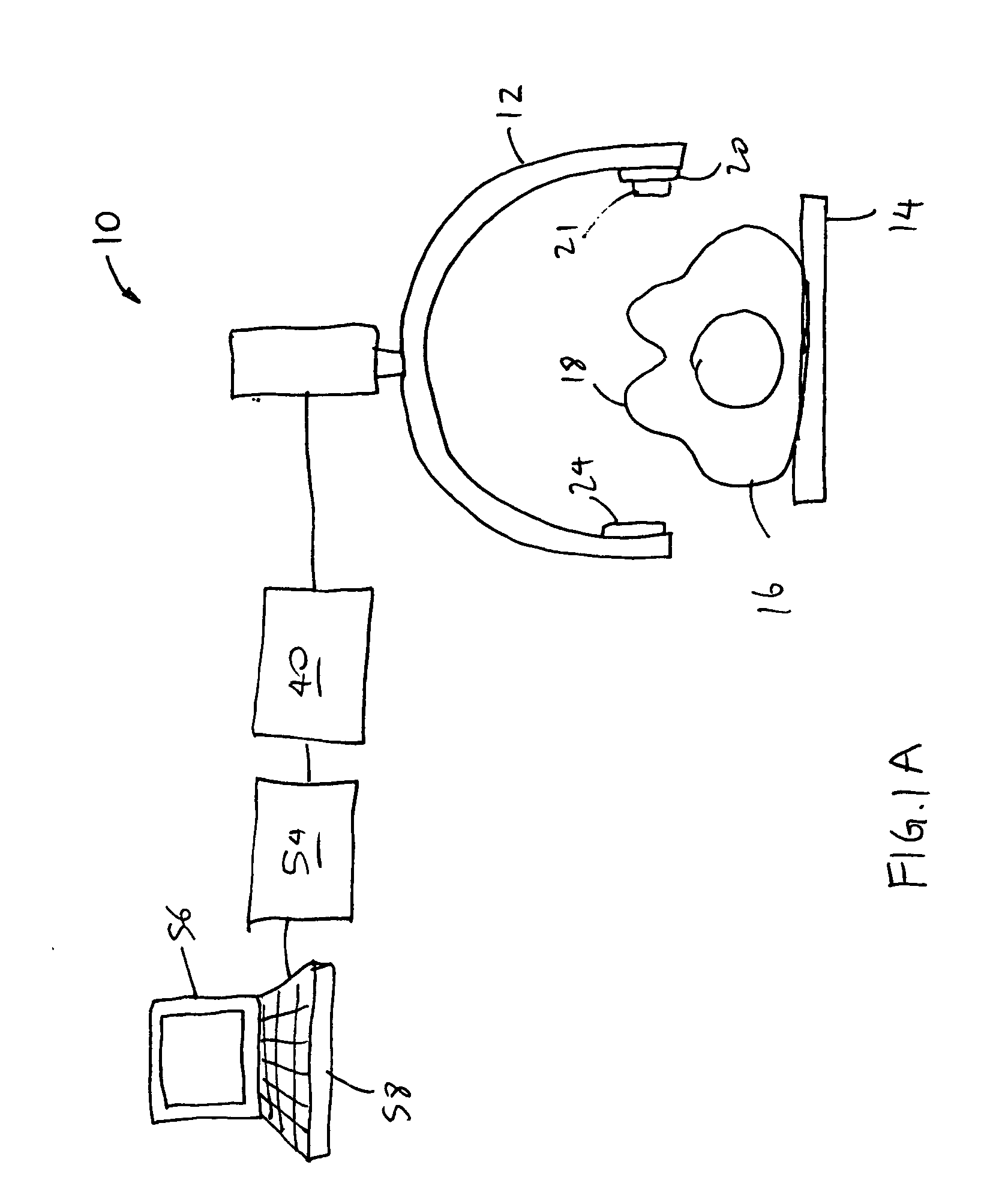
[0024] Referring now to the drawings, in which similar or corresponding parts are identified with the same reference numeral, FIG. 1 illustrates a computed tomography (CT) image acquisition system 10 in accordance with some embodime...


PUM


Abstract

An apparatus for use in a radiation procedure includes a radiation filter having a first portion and a second portion, the first and the second portions forming a layer for filtering radiation impinging thereon, wherein the first portion is made from a first material having a first x-ray filtering characteristic, and the second portion is made from a second material having a second x-ray filtering characteristic. An apparatus for use in a radiation procedure includes a first target material, a second target material, and an accelerator for accelerating particles towards the first target material and the second target material to generate x-rays at a first energy level and a second energy level, respectively.

Description

BACKGROUND OF THE INVENTION [0001] 1. Field of the Invention [0002] This invention relates generally to systems and methods for image acquisition and, more specifically, to systems and methods for angiogenesis imaging using computed tomography. [0003] 2. Background of the Invention [0004] Each year, many women are diagnosed with breast cancer, and the number of deaths associated with breast cancer has reached 40,000 per year. The death toll cannot be substantially reduced because current screening and diagnostic techniques do not detect all cancers at an early enough stage to effectuate a treatment cure. As such, early diagnosis and treatment of breast cancer is highly desirable. [0005] Tumors larger than a few millimeters in cross section generally require a blood supply in order to obtain nutrients and oxygen for growth. Vessels that grow around the tumors proliferate in a disorganized manner and they may leak and pool blood around the tumors. Iodine-contrast-enhanced mammography ...

Claims


Application Information

Patent Timeline
IPC IPC(8): A61BG21K3/00H01J35/10H01J35/14H01J35/28H01J35/30
CPCH01J2235/1006H01J2235/088A61B5/7292A61B6/032A61B6/4035A61B6/405A61B6/482A61B6/502A61B6/5288A61B6/541H01J35/101H01J35/14H01J35/28H01J35/305A61B5/7289H01J35/153
Inventor SEPPI, EDWARD J.VIRSHUP, GARY
Owner VARIAN MEDICAL SYSTEMS
Why Eureka
Try Eureka