Rotary cutting tool, such as a drill, comprising an exchangeable cutting insert, and an exchangeable cutting insert

Active Publication Date: 2005-04-21
KENNAMETAL INC
View PDF39 Cites 52 Cited by
  • Summary
  • Abstract
  • Description
  • Claims
  • Application Information

AI Technical Summary

Benefits of technology

[0009] The problem may be solved in accordance with at least one possible embodiment of the present application. The tool shank of a rotary cutting tool with an exchangeable cutting insert may be provided on the tool circumference with a limb that may be advantageously inclining overall relative to the tool axis. A correspondingly inclining bearing surface of a wing of the cutting insert can engage in said limb or guiding tab. When the cutting insert is rotated into the tool shank, the inclining bearing surfaces on the tool circumference m

Problems solved by technology

This may cause bracing when the cutting insert is rotated into the seat, which may be intensified by cutting at higher cutting forces.
The stability of the mount of the cutting insert on the tool shank and the mechanical load capacity of the drilling tool overall may be restricted thereby.
Said axial force may act

Method used


Image

  • Rotary cutting tool, such as a drill, comprising an exchangeable cutting insert, and an exchangeable cutting insert
  • Rotary cutting tool, such as a drill, comprising an exchangeable cutting insert, and an exchangeable cutting insert
  • Rotary cutting tool, such as a drill, comprising an exchangeable cutting insert, and an exchangeable cutting insert

Examples


Embodiment Construction

[0032] Identical parts are provided with the same reference number in all drawings.

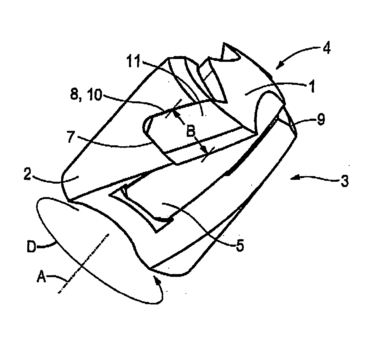
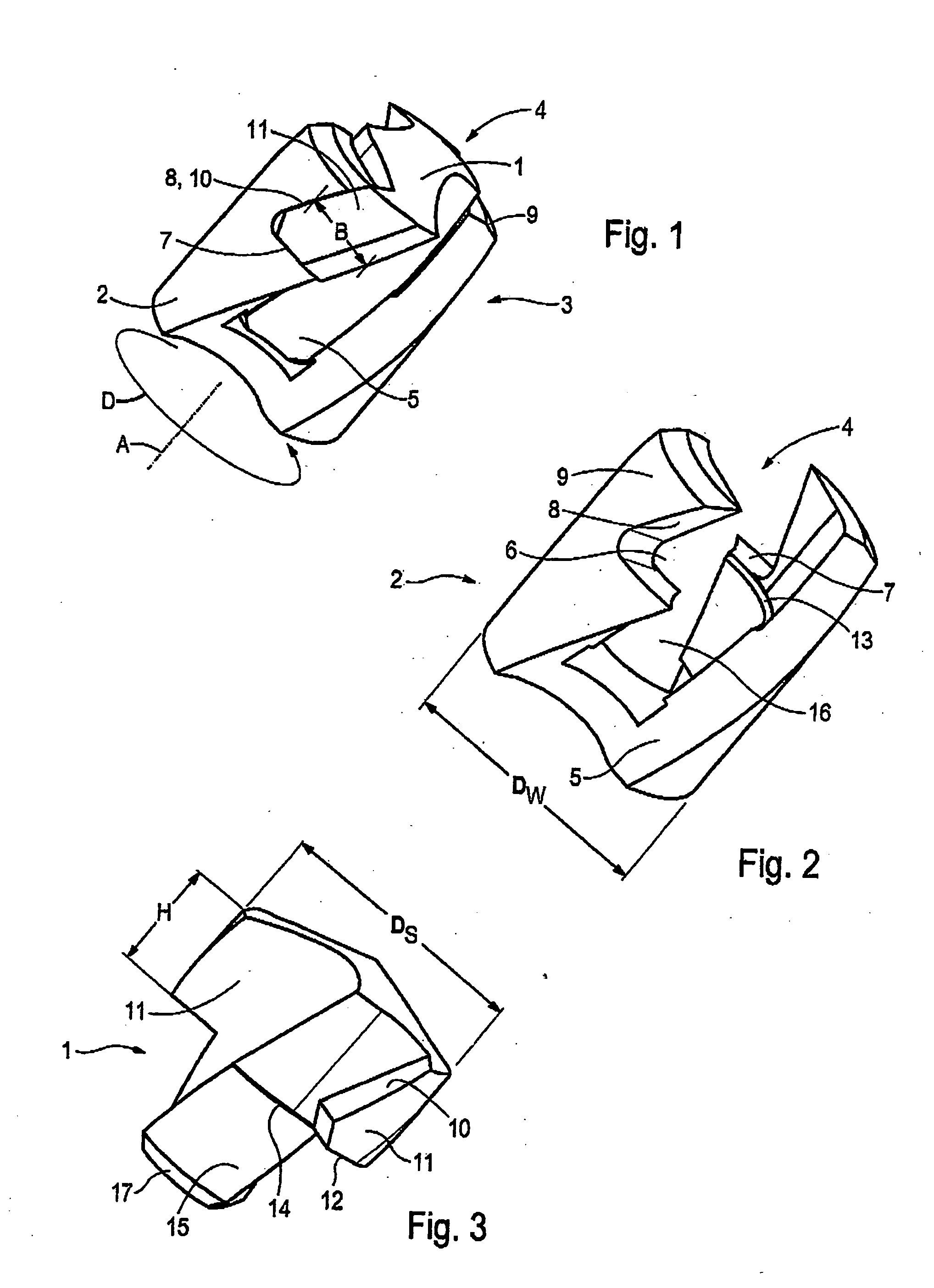
[0033] FIGS. 1 to 3 show a perspective view of a cutting element or cutting insert 1 and a drill shank or tool shank 2 of a rotary cutting tool 3 in the form of a drilling tool. A recessing, milling or reaming tool, for example, may be similarly configured. Especially hard metal, cermet, ceramic and HSS, either coated or uncoated, are the materials used for the cutting insert 1. It is possible to provide a cutting insert 1 with PCD or CBN. The cutting insert 1 is finished either conventionally by polishing, for example, or by means of the so-called “metal injecting molding” (MIM) method. The cutting insert 1 is inserted into the tool shank 3 at the tip 4 of the shank. Both for inserting and releasing the cutting insert 1 from the tool shank 2 a key (not shown) is used. The direction of rotation of the tool is identified by D, the tool or drill axis is identified by A. The tool shank 2, advantageously...


PUM

PropertyMeasurementUnit
Angleaaaaaaaaaa
Angleaaaaaaaaaa
Angleaaaaaaaaaa

Abstract

A rotary cutting tool that is composed of a tool shank with at least one chucking groove or chip flute and one exchangeable cutting insert. At the tip of the shank a recess for accommodating the cutting insert is provided. The tool shank, on its circumference, has a limb with a bearing surface that is inclined relative to the tool axis and that corresponds to a likewise inclined bearing surface on a wing of the cutting insert. The inclination of the bearing surfaces produces an axial force that retains the cutting insert on the tool shank. The abstract of the disclosure is submitted herewith as required by 37 C.F.R. §1.72(b). As stated in 37 C.F.R. §1.72(b): A brief abstract of the technical disclosure in the specification must commence on a separate sheet, preferably following the claims, under the heading “Abstract of the Disclosure.” The purpose of the abstract is to enable the Patent and Trademark Office and the public generally to determine quickly from a cursory inspection the nature and gist of the technical disclosure. The abstract shall not be used for interpreting the scope of the claims. Therefore, any statements made relating to the abstract are not intended to limit the claims in any manner and should not be interpreted as limiting the claims in any manner.

Description

CONTINUING APPLICATION DATA [0001] This application is a Continuation-In-Part application of International Patent Application No. PCT / EP03 / 01526, filed on Feb. 15, 2003, which claims priority from Federal Republic of Germany Patent Application No. 102 07 257.4, filed on Feb. 21, 2002. International Patent Application No. PCT / EP03 / 01526 was pending as of the filing date of this application. The United States was an elected state in International Patent Application No. PCT / EP03 / 01526.BACKGROUND [0002] 1. Technical Field [0003] This application relates to a rotary cutting tool, especially a drilling tool, composed of a tool shank and an exchangeable cutting insert. The tool shank, on its circumference, is provided with a limb with a bearing surface bordering on the circumference of the tool shank and inclined relative to the tool axis and corresponding to a likewise inclined bearing surface on a wing of the cutting insert. The orientation of the inclination of the bearing surfaces corr...

Claims


Application Information

Patent Timeline
IPC IPC(8): B23B51/00B23B51/02B23C5/10B23D77/02
CPCB23B51/02Y10T408/9095B23B2251/02B23B2251/50B23C5/109B23D77/025B23D2277/02B23B51/00Y10S408/713Y10T408/907Y10T408/9098Y10T408/9097Y10T408/909Y10T408/892B23B2205/02B23C5/10B23D77/02
Inventor BORSCHERT, BERNHARDMUHLFRIEDEL, DIETERSCHWAGERL, JURGENDE SOUZA FILHO, RUY FROTASHULTZ, MICHAEL D.MCCORMICK, MICHAEL R.ERICKSON, ROBERT A.
Owner KENNAMETAL INC
Why Eureka
Try Eureka