Eureka AIR delivers breakthrough ideas for toughest innovation challenges, trusted by R&D personnel around the world.

Interlayer design for magnetic media

Inactive Publication Date: 2005-04-21
SEAGATE TECH LLC
View PDF4 Cites 11 Cited by
  • Summary
  • Abstract
  • Description
  • Claims
  • Application Information

AI Technical Summary

Benefits of technology

[0012] One variation comprises a non-oxidized or oxidized NiP layer on the substrate. Preferably, the magnetic layer comprises CoCr or an alloy of CoCr with at least one element selected from the group consisting of Pt, Ta, B, Mo, Ru, Si, Ge, Nb, Fe, Ni and combinations thereof. More preferably, the magnetic layer comprises (a) a Cr-rich layer of Co100-δCrδ or Co100-δCrδX, wherein δ>ε and X is an element selected from the grou

Problems solved by technology

However, there are limits to how small the bits may be made.
If the bit becomes too small, the magnetic energy holding the bit in place may become so small that thermal energy may cause it to demagnetize over time.
However, the fields that can be applied are limited by the magnetic materials from which the head is made, and these limits are being approached.
A great challenge however is maintaining a strong signal for the bits recorded on the media.
When the bit size is reduced, the signal is decreased, making the bits more difficult to detect, as well as more difficult to maintain stable after recording information.
One of the key challenges to extending magnetic recording technology beyond the currently achieved 35-100 Gbit / in2 areal densities is to improve the signal to noise ratio by media noise suppression.
It is well known that the longitudinal scaling approach, which is to reduce the media grain surface area in proportion to the bit cell surface area, is limited by the onset of super-paramagnetic instability, which is explained above.
Traditionally, one has compensated the loss in grain volume by increasing the magnetic hardness (anisotropy); however, the write field of the recording head limits this approach.
The extendibility of this approach, however, appears to be rather limited.
This approach could lead to higher media noise and would, among many other things, require significantly improved channel detectors.
Thus, it remains an open challenge to bring out the required improvements in grain size and grain size distribution using physical, thin film sputtering processes.

Method used


Image

  • Interlayer design for magnetic media
  • Interlayer design for magnetic media
  • Interlayer design for magnetic media

Examples


examples

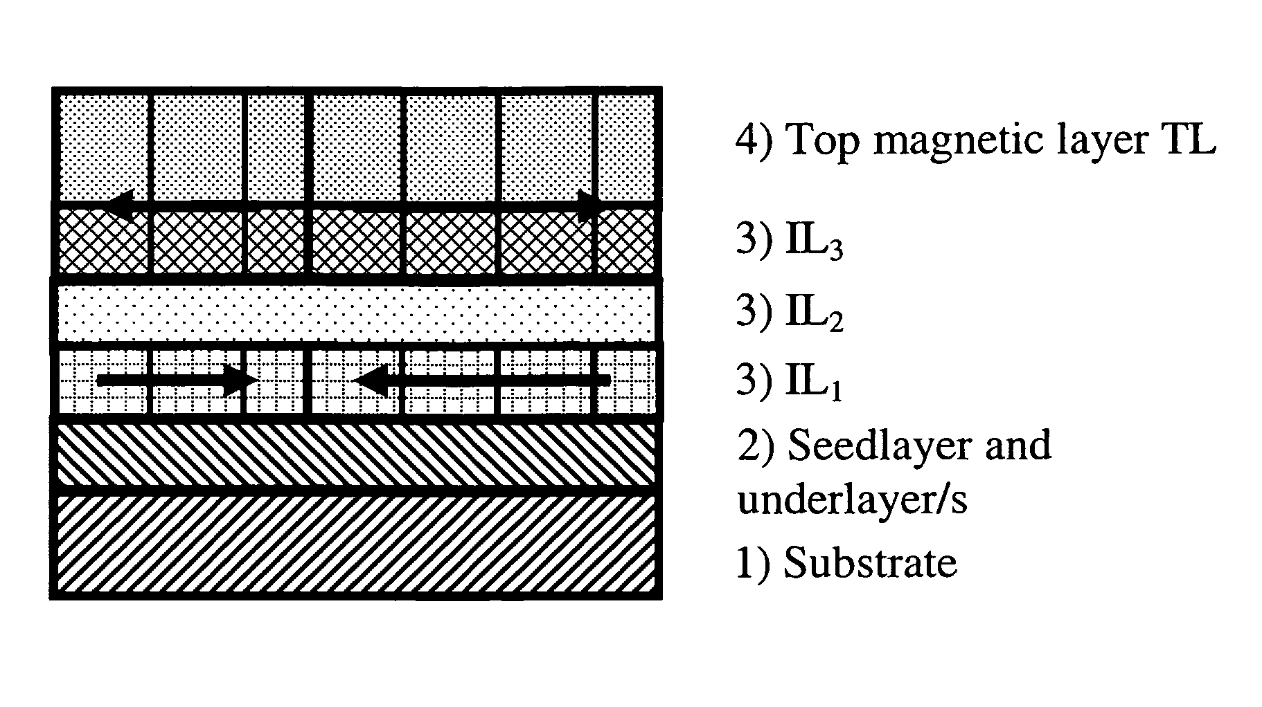
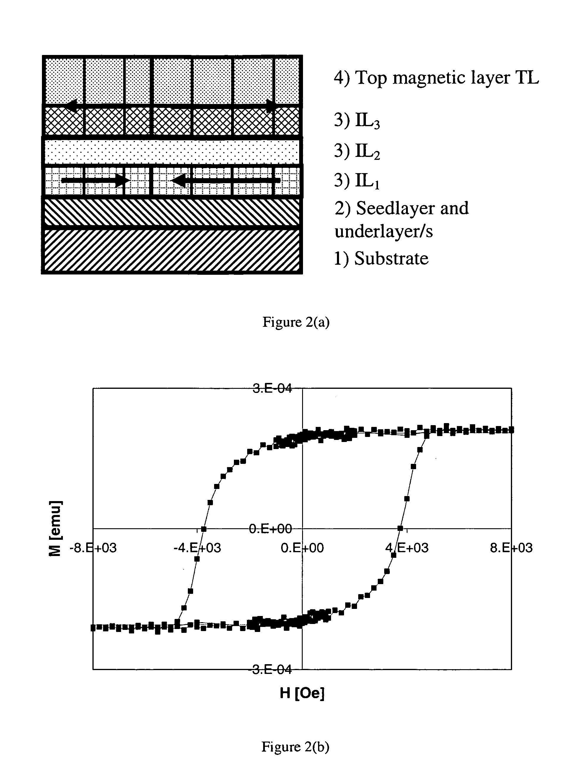
[0054] Longitudinal media, AFC media and QAFC media were prepared with following media structures: [0055] Longitudinal media: Cr based underlayers / IL / TL [0056] AFC media: Cr based underlayers / BL / Ru / IL / TL [0057] New media design, QAFC: Cr based underlayers / IL1 / IL2(Ru) / IL3 / TL

The IL1 in the new media design is much thinner than BL in AFC and similar in composition. IL3 in QAFC is several times thicker than IL in AFC and similar in composition. TL has the same composition in all three media structures. IL3 in QAFC and IL in longitudinal media have similar thickness and composition. However, the relative contribution of IL1 to total Mrt of QAFC is significantly larger than the relative contribution of IL to total Mrt of longitudinal media. In longitudinal media IL grows on top of a Cr-rich layer with bcc crystal structure. This causes formation of a thin transition layer at the interface between bcc and hcp crystal structures that does not contribute to media Mrt. On the other hand, in...


PUM


Abstract

A magnetic recording medium having a substrate, an interlayer and a magnetic layer, the interlayer having at least a first intermediary layer, a second intermediary layer and a third intermediary layer, wherein the first intermediary layer or the third intermediary layer is non-magnetic or magnetic and the second intermediary layer has a hexagonal close pack crystal structure and a property of providing RKKY coupling between the first intermediary layer and the third intermediary layer when the first intermediary layer and the second intermediary layer are magnetic layers is disclosed.

Description

RELATED APPLICATIONS [0001] This application claims benefit from Provisional Application Ser. No. 60 / 511,651 filed Oct. 17, 2003, the entire disclosure of the above mentioned application is hereby incorporated herein by reference.FIELD OF INVENTION [0002] The present invention relates to the recording, storage and reading of magnetic data, particularly magnetic recording media having a structure substantially similar to that of anti-ferromagnetically coupled (AFC) media. BACKGROUND [0003] Magnetic disks and disk drives are conventionally employed for storing data in magnetizable form. Preferably, one or more disks are rotated on a central axis in combination with data transducing heads positioned in close proximity to the recording surfaces of the disks and moved generally radially with respect thereto. Magnetic disks are usually housed in a magnetic disk unit in a stationary state with a magnetic head having a specific load elastically in contact with and pressed against the surfac...

Claims


Application Information

Patent Timeline
IPC IPC(8): G11B5/64G11B5/66
CPCG11B5/656Y10T428/265G11B5/66G11B5/672
Inventor GIRT, EROLROU, ALEXWANG, JOHN
Owner SEAGATE TECH LLC
Why Eureka
Eureka Blog
Learn More