Magnetic Tunnel Junctions Using Amorphous Materials as Reference and Free Layers

Active Publication Date: 2006-05-11
IBM CORP
View PDF50 Cites 138 Cited by
  • Summary
  • Abstract
  • Description
  • Claims
  • Application Information

AI Technical Summary

Benefits of technology

[0026] Performance of the MgO (or Mg—ZnO) tunnel barriers disclosed herein may be improved through annealing, wherein performance refers to various attributes of the tunnel barrier or associated device. For example, annealing a magnetic tunnel junction improves, in particular, its magneto-tunneling resistance; annealing a tunnel barrier improves, in particular, its spin polarization. In particular by annealing these tunnel barriers, tunneling magneto-resistance of more than 100% can readily be ach

Problems solved by technology

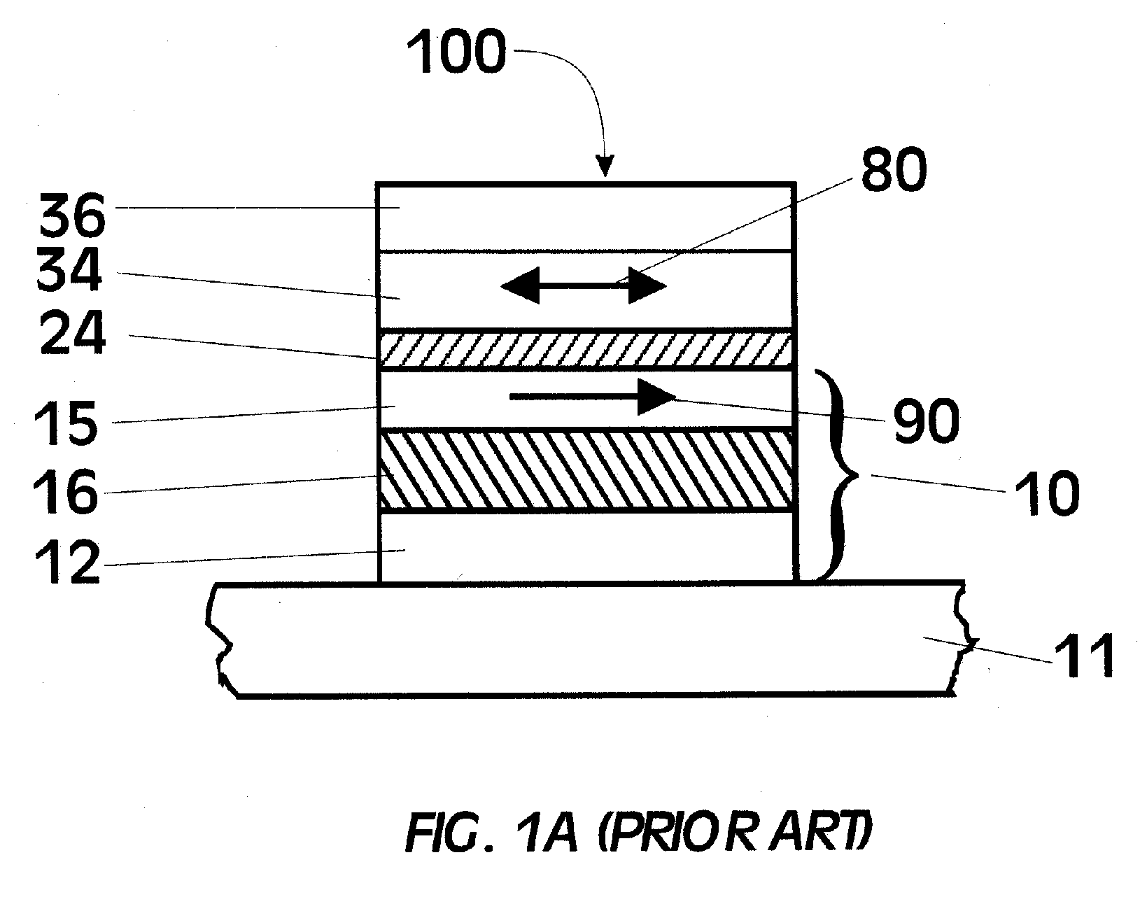
This leads to very large self-demagnetizing for devices which are not circular in cross-section and very large magnetostatic coupling fields between ferromagnetic layers in the same device.
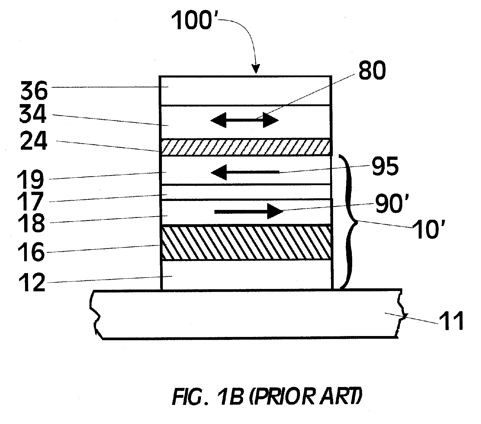
However, MTJs with MgO tunnel barriers and synthetic antiferromagnetic reference layers using Ru antiferromagnetic coupling layers do not exhibit the high tunneling magnetoresistance values exhibited by similar MTJs without the synthetic antiferromagnetic reference layer.
MTJs without a synthetic antiferromagnetic reference layer suffer from the presence of unwanted coupling fields, as discussed above, since the storage magnetic layer moment has a tendency to be aligned anti-parallel to the reference layer magnetic moment.
One of the mos

Method used


Image

  • Magnetic Tunnel Junctions Using Amorphous Materials as Reference and Free Layers
  • Magnetic Tunnel Junctions Using Amorphous Materials as Reference and Free Layers
  • Magnetic Tunnel Junctions Using Amorphous Materials as Reference and Free Layers

Examples


Embodiment Construction

[0049] The tunneling current in an MTJ is spin polarized, which means that the electrical current passing from one of the ferromagnetic layers is predominantly composed of electrons of one spin type (spin up or spin down, depending on the orientation of the magnetization of the ferromagnetic layer). The tunneling spin polarization P of the current can be inferred from a variety of different measurements. The measurement most relevant to magnetic tunneling is to measure the conductance as a function of bias voltage for junctions formed from a sandwich of the ferromagnetic material of interest and a superconducting counter electrode (R. Meservey and P. M. Tedrow, Phys. Rep. 238, 173 (1994)). These studies show that the spin polarization of the tunnel current measured in this way can be simply related to the TMR close to zero bias voltage as first proposed by julliére (M. Julliére, Phys. Lett. 54A, 225 (1975)). In such a model P is defined as

(n↑−n↓) / (n↑+n↓)

where

n↑

and

n↓

are the dens...


PUM


Abstract

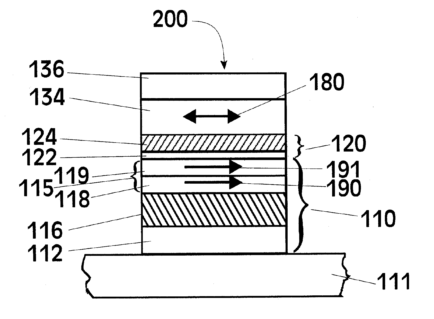
Magnetic tunnel junctions are constructed from a MgO or Mg—ZnO tunnel barrier and amorphous magnetic layers in proximity with, and on respective sides of, the tunnel barrier. The amorphous magnetic layer preferably includes Co and at least one additional element selected to make the layer amorphous, such as boron. Magnetic tunnel junctions formed from the amorphous magnetic layers and the tunnel barrier have tunneling magnetoresistance values of up to 200% or more.

Description

[0001] The U.S. Government has a paid-up license in this invention and the right in limited circumstances to require the patent owner to license others on reasonable terms as provided for by the terms of contract MDA972-01-C-0051 awarded by DARPA.TECHNICAL FIELD [0002] The invention relates to magnetic tunnel junction (MTJ) magnetoresistive (MR) devices for use as magnetic field sensors such as read heads for reading magnetically recorded data, as memory cells in nonvolatile magnetic random access memory (MRAM) cells, and for magnetic logic and spintronic applications. More particularly, this invention relates to an improved MTJ exhibiting high tunneling magnetoresistance with one or more electrodes formed from amorphous ferromagnetic materials. BACKGROUND OF THE INVENTION [0003] The basic component of a magnetic tunnel junction is a sandwich of two thin ferromagnetic and / or ferrimagnetic layers separated by a very thin insulating layer through which electrons can tunnel. The tunnel...

Claims


Application Information

Patent Timeline
IPC IPC(8): G11B5/33G11B5/127
CPCB82Y10/00B82Y25/00G11B5/3903G11B5/3909Y10T428/1121H01L43/12Y10T428/1193Y10T428/1114Y10T428/115H01L43/08H10N50/10H10N50/01
Inventor PARKIN, STUART STEPHEN PAPWOTH
Owner IBM CORP
Why Eureka
Try Eureka