Microfabricated system for magnetic field generation and focusing

a technology of magnetic field generation and focusing, applied in the direction of magnetic materials, transformers/inductance coils/windings/connections, optical light guides, etc., can solve the problems of poor selectivity, large force generation of magnetic devices, and general avoidance of magnetically actuated transducers

Inactive Publication Date: 2005-12-15
AGENCY FOR SCI TECH & RES +1
View PDF6 Cites 142 Cited by
  • Summary
  • Abstract
  • Description
  • Claims
  • Application Information

AI Technical Summary

Benefits of technology

[0039] An eighth object of the present invention is to provide an inductor that can be easily integrated into various forms of RF and HF communication circuitry.
[0044] A thirteenth object of the present invention is to provide a method of fabricating such micro-coils on or in a Si substrate, the high thermal conductivity of such a substrate providing a particularly effective heat dissipation and removal mechanism.
[0045] The objects of the present invention will be achieved by the formation of planar micro-coils and arrays of such coils, that are formed on or embedded in either a silicon or a dielectric polymeric substrate and are formed of conductors having a cross-sectional shape with large area and high thickness-to-width aspect ratio (typically 10 / 3, but 9 / 3, 11 / 3 or any aspect ratio greater than 3 / 1 is also acceptable), i.e., characterized by a thickness (vertical dimension) that is substantially larger than a width (horizontal dimension). The micro-coils so formed typically comprise two components, (1) a planar micro-coil formed of Cu electroplated onto or into a Si or polymeric substrate; and (2) a structure serving the purpose of a flux-concentrating magnetic core, the structure being a ferromagnetic pillar, formed by electroless plating of a highly permeable ferromagnetic material, preferably NiCoP, but not limited to that material, on the upper surface of the coil, the pillar thereby playing a field (or flux) concentrating role similar to that played by magnetic cores in macroscopic coils. In some of the embodiments there will also be a magnetic back-plate formed on the backside of the micro-coil and, thereby, providing increased magnetic flux closure. It is noted that the silicon substrate is an excellent heat-sink and, further, that the dielectric polymer can offer dielectric property advantages over the silicon. In addition, the silicon can be easily planarized, enabling additional processing to be carried out efficiently and allowing additional circuitry to be integrated with the micro-coils.
[0051] The micro-coils can be arranged in series arrays or parallel arrays, such arrays allowing adjustment of the magnetic fields and gradients by tuning the injected current. The ferromagnetic pillars, which play a field-concentrating role similar to the cores of macroscopic coils, are placed at the location of magnetic field maxima of each micro-coil. As a result, the magnetic field is focused at these specific locations and steep magnetic potential wells can be created. The micro-coils generate the magnetic fields necessary to magnetize the magnetic material forming the pillars and, because they are paths of low reluctance (highly permeable), once the pillars are magnetized, the magnetic lines of flux will be concentrated through them. Hence, the magnetic field at the location of the pillar will be of greatest magnitude and the magnetic gradient at that location will also be great because the flux diminishes rapidly in the region outside of the pillar. Thus, a deep potential well is established in the immediate vicinity of the pillar. An additional advantage offered by the arrays is that the local maxima of the magnetic field can be shifted from point to point on the device surface by properly controlling the current in the array.

Problems solved by technology

On the other hand, the fabrication of magnetically actuated transducers has generally been avoided due to lack of processing knowledge and the difficulty of integrating magnetic components with other microsystems and circuits.
Magnetic devices can generate large forces at larger distances than electrostatic devices, which only exert large forces at small distances.
In the case of electrostatic devices, the electrostatic forces are exerted (unequally) on both the target and other objects in the sample, leading to unavoidable attraction of undesired particles together with the target, thus resulting in poor selectivity.
It is well known, however, that it is a challenging, time consuming and expensive task to construct micro-coils using classical methods, or to hand-machine large pieces of permanent magnetic material into micro-permanent magnets, for the purposes of constructing micro-devices.
The fabrication of micro-coils, in particular, poses critical problems, because the coils are three-dimensional and micro-fabrication is typically two-dimensional.
(2) The final micro-coil has a non-planar upper surface, which can adversely affect subsequent processing steps and integration of additional components.
The coil does not have a magnetic core, which results in significant flux leakage.
The design of these types of micro-coils suffer from several limitations, the most severe being the photolithographic processes required to form high aspect-ratio electroplating molds from the photoresist layers.
Finally, the micro-coils formed by the method have a size on the order of millimeters, which limits their ability to produce the desired magnetic field gradients.
The large number of vias required to interconnect all sections of the coil dramatically increases the coil resistance, limits the magnitude of the current that can be injected and, therefore, limits the maximum magnetic flux density.
The performance of such a fabrication is limited both by the number of turns that can be wound around the magnetic core and the feasibility of integrating the fabrication to other microcomponents.
The nature of the PCB may not permit the device to operate at high current densities.
An additional problem arises from the fact that the ferromagnetic material forming the core is nickel that is deposited by electroplating or electroless plating.
As can be seen from the above citations, there are several limitations and disadvantages to be found in prior art structures and methods which can be summarized as follows: (1) The dimensions of the fabrications produce limited magnetic field gradients and, in consequence, limited magnetic forces.
(2) The designs are basically scaled down versions of macroscopic designs and, as such, require complicated fabrication processes.
(3) The problems associated with the complicated designs and process steps also result in uneven surfaces, which is a disadvantage when subsequent process steps are required.
(4) None of the prior art methods are able to efficiently generate high magnetic field gradients along with planarized surfaces compatible with the integration of additional circuitry and components on the same chip.

Method used


Image

  • Microfabricated system for magnetic field generation and focusing
  • Microfabricated system for magnetic field generation and focusing
  • Microfabricated system for magnetic field generation and focusing

Examples


Embodiment Construction

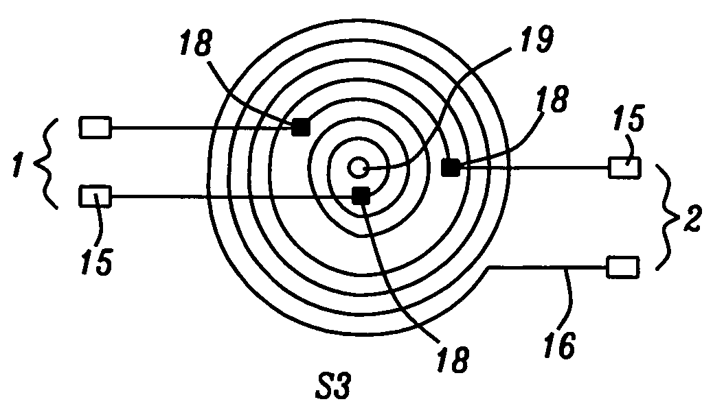
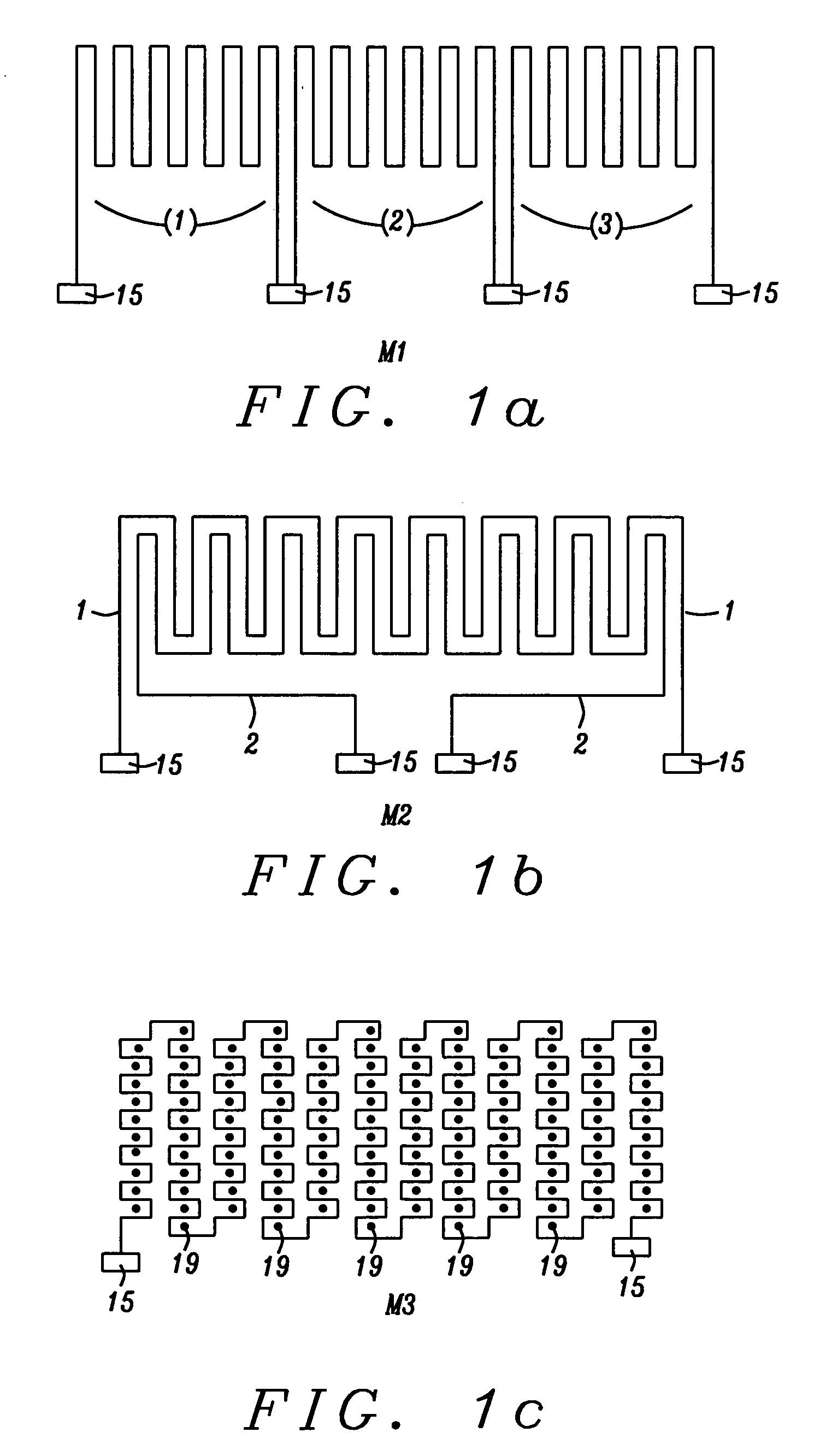
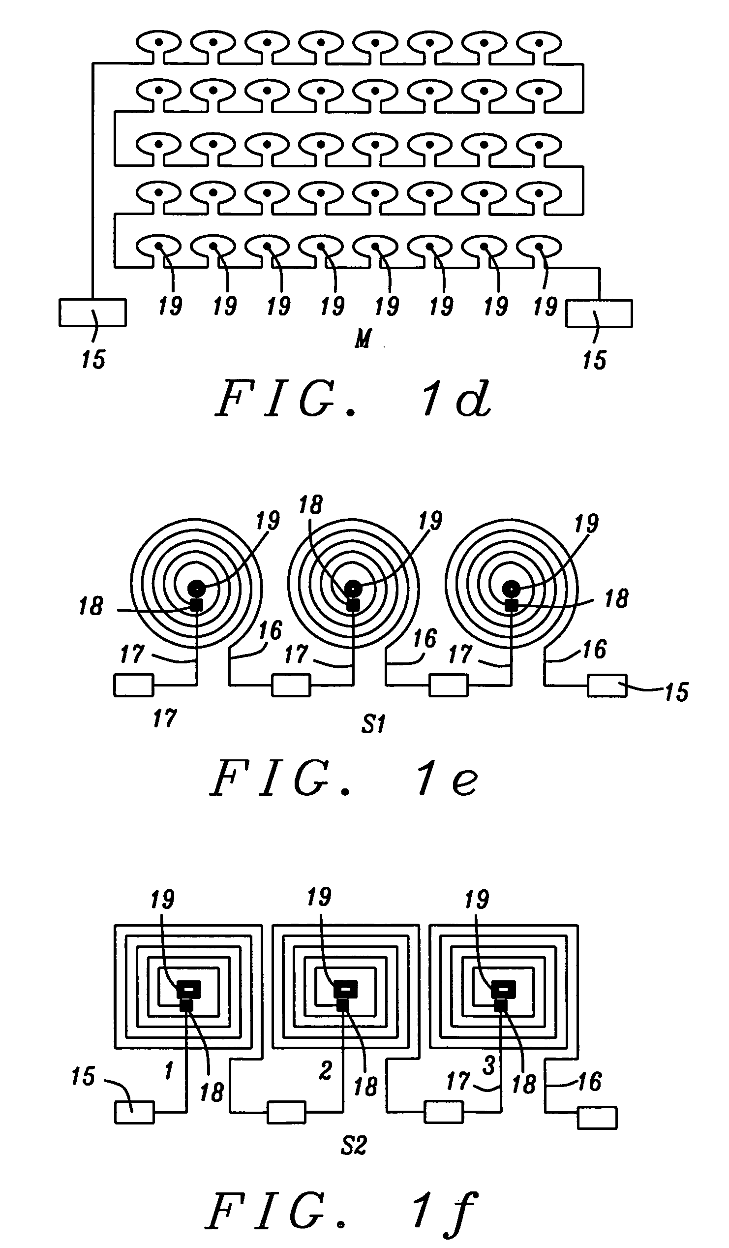
[0062] The present invention, in each of its embodiments, provides a method of fabricating micro-coils and arrays of micro-coils in and on silicon substrates and embedded within dielectric polymer layers formed on the substrates (and the coils and arrays so fabricated), with and without flux-concentrating magnetic pillars and back-plates. These micro-coils and their arrays produce magnetic fields of large magnitude on the order of 0.1 T and large gradients on the order of 103 T / m and are, therefore, suited for a wide range of applications that require the exertion of strong magnetic forces at small distances. In this sense, the micro-coils are micro-electromagnets. In addition, the micro-coils are micro-inductors and micro-receivers and micro-transmitters of electromagnetic energy. The descriptions given below will first describe the geometric designs of the embodiments, with reference to FIGS. 1a-j and FIG. 2. A second section will then describe the method of fabrication of the emb...


PUM

PropertyMeasurementUnit
depthaaaaaaaaaa
depthaaaaaaaaaa
thicknessaaaaaaaaaa

Abstract

A method of forming, in or on a Si substrate, planar micro-coils with coil windings of high aspect ratio (>3) and a wide variety of geometric shapes. The micro-coils may be formed on a Si substrate and be embedded in a dielectric, or they may be formed in trenches within a Si substrate. The micro-coils may have field enhancing ferromagnetic pillars rising above the micro-coil plane, formed at positions of maximum magnetic field strength and the micro-coils may also include magnetic layers formed beneath the substrate and contacting the pillars to form a substantially closed pathway for the magnetic flux. The substrate may be thinned to membrane proportions. These micro-coils produce strong magnetic fields with strong field gradients and can be used in a wide variety of processes that involve the exertion of strong magnetic forces at small distances or the creation of magnetic wells for trapping and manipulating small particles.

Description

PRIORITY [0001] This Application claims the priority of the Provisional Application, Ser. No. 60 / 578,416, Filing Date Jun. 9, 2004, which is fully incorporated herein by reference.BACKGROUND OF THE INVENTION [0002] 1. Field of the Invention [0003] This invention relates generally to the fabrication of micro electromagnetic devices such as micro electromagnetic coils, which can be used as transducers within micro electromechanical systems (MEMS). [0004] 2. Description of the Related Art [0005] The majority of MEMS transducers have been electrostatically driven due to their ease of fabrication and integration with other micro components. On the other hand, the fabrication of magnetically actuated transducers has generally been avoided due to lack of processing knowledge and the difficulty of integrating magnetic components with other microsystems and circuits. In spite of poor scaling of magnetic forces, there is at present a growing interest in magnetic micro-devices, mainly due to t...

Claims


Application Information

Patent Timeline
Patent Type & Authority Applications(United States)
IPC IPC(8): B81B7/02B81C1/00H01F5/04H01F41/04H01H50/00H01H51/22H01L21/68
CPCH01F5/003H01F41/046H01F2007/062H01F2007/068H01F2017/0086H01H50/005H01L23/5227H01L23/645H01L2924/3011H01L2924/0002H01L2924/00B81B7/02B81C1/00H01F5/04H01F41/04
Inventor RAMADAN, QASEMSAMPER, VICTORPOENAR, DANIEL PUIUYU, CHEN
Owner AGENCY FOR SCI TECH & RES
Why Eureka
Try Eureka