
Ultrasound apparatus and method for augmented clot lysis

a technology of ultrasonic equipment and augmented clot, which is applied in the field of ultrasonic equipment and methods for augmented clot lysis, can solve the problems of physical stress and temperature increase in the targeted tissue, and achieve the effect of improving the quality of life and reducing the risk of clot formation

Active Publication Date: 2005-04-21
THE BOARD OF TRUSTEES OF THE UNIV OF ARKANSAS
View PDF22 Cites 94 Cited by
  • Summary
  • Abstract
  • Description
  • Claims
  • Application Information

AI Technical Summary

Benefits of technology

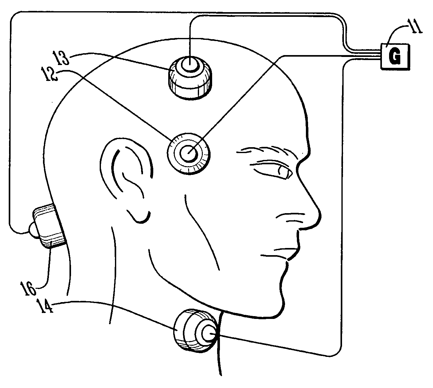
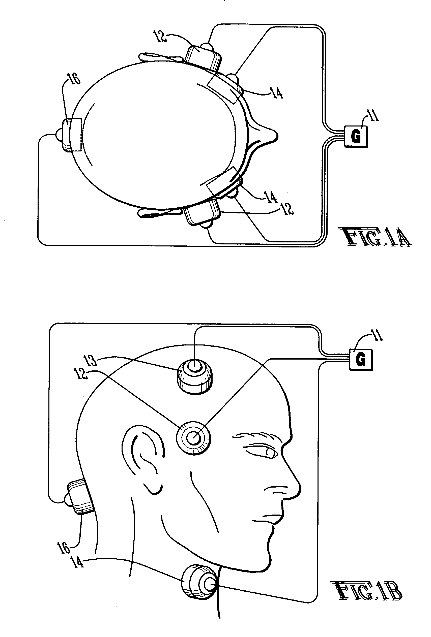
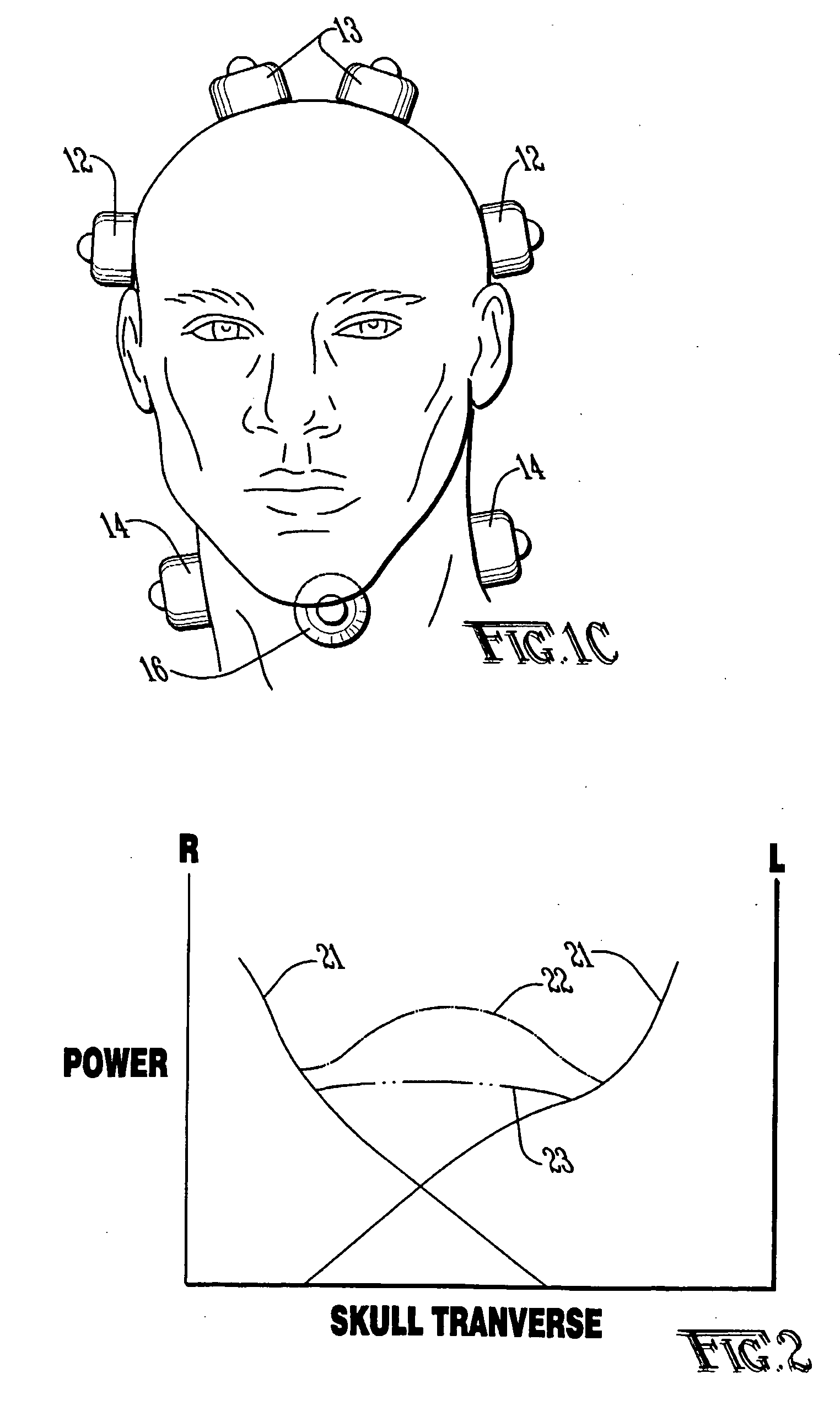
[0009] The present invention overcomes the problems of the prior art by using one or more ultrasound transducers generating a plurality of acoustic signals at similar or different frequencies to produce traveling interference patterns. Also, the frequency, amplitude and phase from the transducers may be modulated so that any interference pattern will be constantly shifting in position, thereby insuring uniform coverage. In one embodiment, a phased array of transducers may generate a beam that is swept over the area to be treated. In another embodiment, an array of transducers may generate ultrasound at a number of slightly varying frequencies to produce an interference pattern that sweeps in and out through the targeted tissue. A single array may be used to produce both effects simultaneously or separately.
[0010] At high power, ultrasound causes physical stresses and a temperature increase within the targeted tissue. The amplitude of the excitation voltage may be manipulated to reduce the heating effect. By using a gating circuit, short bursts of ultrasound may be produced so that the average power delivered to the targeted tissue may be reduced while the intensity of the ultrasound may be kept relatively high during the short ultrasound burst. Further, when microbubbles are employed as the lysing agent, the duration between the ultrasound bursts may be adjusted so as to allow even minimal blood flow to replenish the supply of microbubbles at the surface of the clot that will have been ruptured by the ultrasonic action. As noted above, certain embodiments of the invention may use phased arrays of transducers to move an ultrasound beam around the targeted tissue. Likewise, one or more transducers may generate a plurality of varying frequencies to produce interference patterns of traveling waves of ultrasound that sweep through the targeted tissue. A gating circuit may not be required when either of these embodiments or a combination allow the average power lever to be kept low enough in the targeted tissue to avoid overheating.
[0011] Variations in the spatial arrangement of the transducers may be used to change the field shape. The transducers may be moved to continually vary the field. Also, the beam from the ultrasound transducers may be designed in such a way that the beam is dispersed at wide angles, obviating the need for an ultrasound transducer to be aimed directly at a clot. Focusing devices or phased array technology may be used to more widely disperse the beam in a “search light sweep” manner. In one embodiment of the present invention, an array of a large number of transducers would have each transducer excited by a slightly different frequency. The resulting pressure waveform would have periodic large peaks with less average power and the pressure peaks would sweep through the targeted tissue in an in and out manner. Also, by sequenced phasing across the array such that each transducer is driven at the same frequency but differing in phase, this phased array could direct the beam through a wide volume of targeted tissue without moving the transducers. By combining these two embodiments, the resulting maxima and minima of the power deposition moving rapidly through all points in the beam while the beam is sweeping the targeted tissue would result in a much better penetration by this focused beam than by a diffused beam.

Problems solved by technology

At high power, ultrasound causes physical stresses and a temperature increase within the targeted tissue.

Method used


Image

  • Ultrasound apparatus and method for augmented clot lysis
  • Ultrasound apparatus and method for augmented clot lysis
  • Ultrasound apparatus and method for augmented clot lysis

Examples


Embodiment Construction

[0021] Known therapeutic ultrasound thrombolysis techniques based on microbubbles, thrombolytic drugs or the like lysing a clot in ultrasound fields are limited in field size and range. Also, ultrasound is absorbed by tissue. Multiple transducers decrease the problems of shadowing and suboptimal energy levels seen with single transducers. The present invention overcomes the limitations of the prior art by using one or more transducers and by frequency, phase and timing modulation of a plurality of acoustic signals to provide more uniform power delivery through traveling waves without the gaps in the fields caused by standing waves. The ultrasound field is manipulated, both temporally and spatially, to maximize both effect and ease of use. Wide application to stroke and problem clots in various applications is expected.

[0022] The present invention is unique in that it may be effective in treating ischemic stroke in the human brain where the technique of lysing clots with microbubble...


PUM


Abstract

An apparatus and method for using ultrasound augmented with microbubbles, thrombolytic drugs or other agents for clot lysis wherein at least one ultrasound transducer generates a plurality of acoustic signals and time, amplitude, phase and frequency modulation of the signals provide more uniform power delivery with fewer gaps in the ultrasound field. Interference patterns from one or multiple transducers are constantly shifted in position. A phased array of transducers may generate a beam that is swept over the area to be treated. In another embodiment, an array of transducers may generate ultrasound at a number of slightly varying frequencies to produce an interference pattern that sweeps in and out through the targeted tissue. A single array may be used to produce both effects simultaneously or separately.

Description

CROSS-REFERENCE TO RELATED APPLICATIONS [0001] This application claims the benefit of U.S. Provisional Application No. 60 / 501,000 filed Sep. 8, 2003, the disclosure of which is incorporated herein by reference.STATEMENT REGARDING FEDERALLY SPONSORED RESEARCH OR DEVELOPMENT [0002] Not applicable. BACKGROUND OF THE INVENTION [0003] The present invention relates to an apparatus and method for using ultrasound augmented with microbubbles, thrombolytic drugs or other lysing agents for clot lysis, and in particular to such an apparatus and method using time, phase and frequency modulation of multiple acoustic signals from one or more ultrasound transducers to provide uniform power delivery with fewer gaps in the ultrasound field. [0004] Thrombosis is the development of a blood clot within a blood vessel. A thrombosis can cause serious, even life threatening, conditions due to partial or total blockage of a blood vessel. Various techniques are known for lysing or removal of the clot. These...

Claims


Application Information

Patent Timeline
IPC IPC(8): A61BA61B8/00A61B17/22A61N7/00A61N7/02
CPCA61B17/22004A61B2017/22008A61B2017/22027A61B2017/22084A61N2007/0095A61N7/02A61N2007/0073A61N2007/0078A61B2017/22089
Inventor CULP, WILLIAM C.WILSON, JAMES D.
Owner THE BOARD OF TRUSTEES OF THE UNIV OF ARKANSAS
Learn More