
Method and apparatus for forming cast wall panels

Inactive Publication Date: 2005-04-28
LJB
View PDF24 Cites 23 Cited by
  • Summary
  • Abstract
  • Description
  • Claims
  • Application Information

AI Technical Summary

Benefits of technology

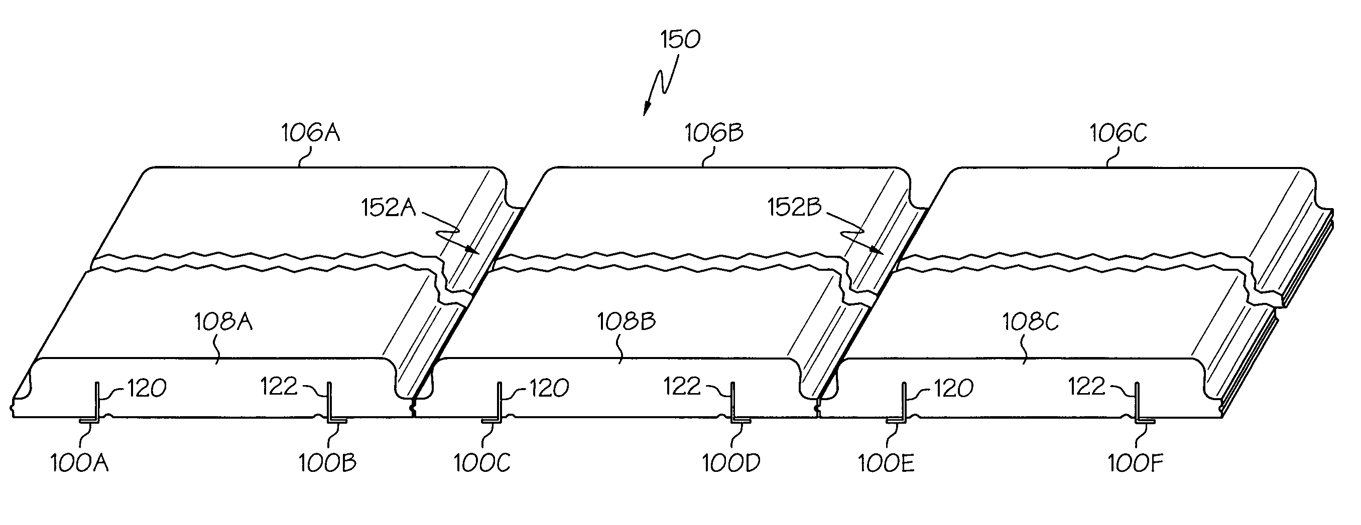
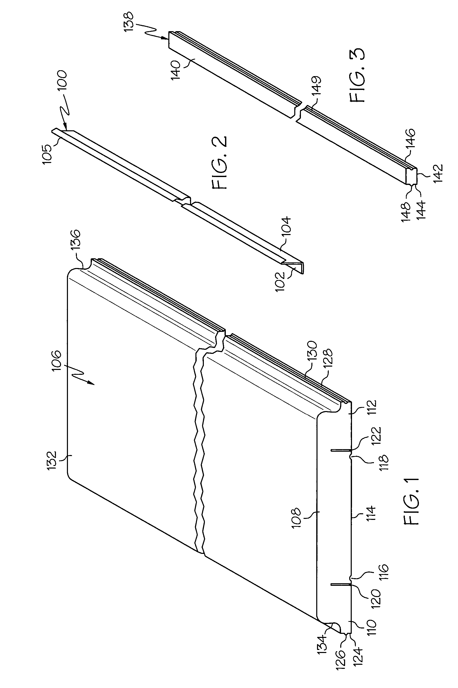
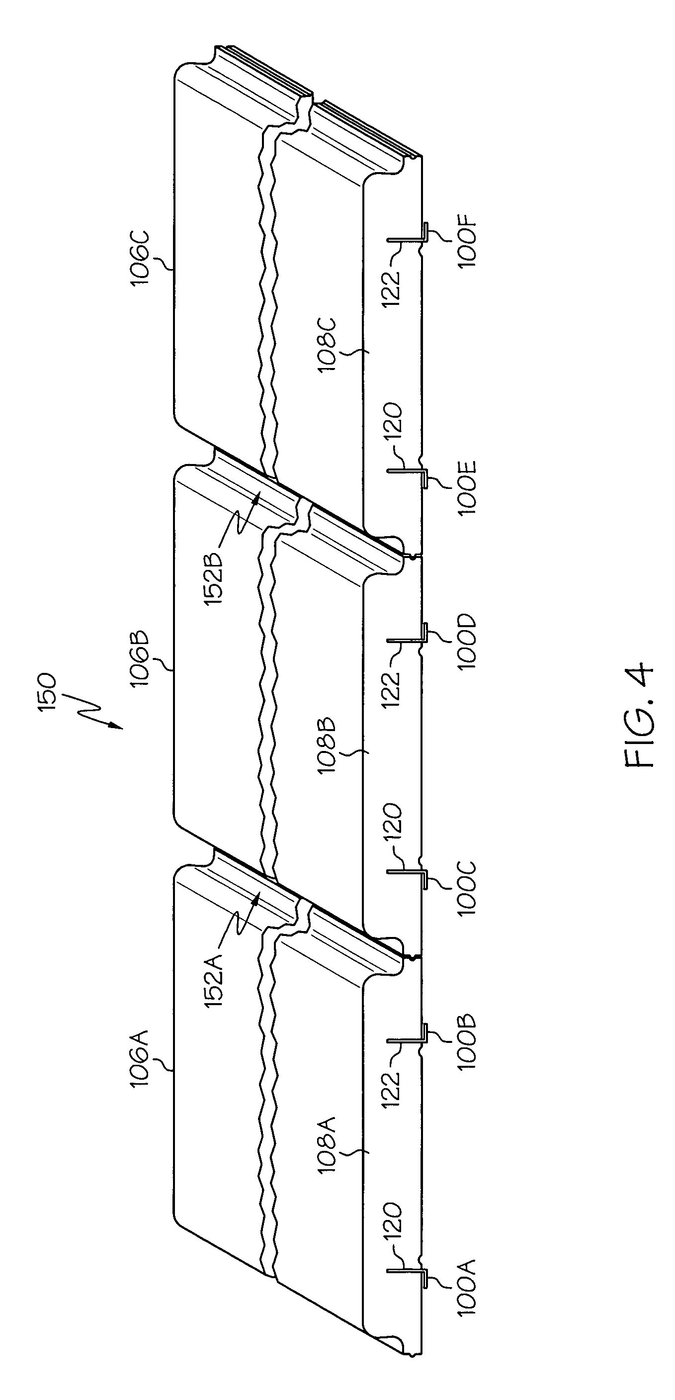
[0007] The apparatus of the invention preferably includes a wall panel made up of a foam insulation layer or wythe and a structural wythe, preferably made of cast concrete. The insulation wythe is made up of a series of planks, each having a body and a pair of opposing flanges. The flanges preferably include surfaces on which a tongue or a groove is formed so that the planks may be placed side-by-side and engage each other along adjacent flanges with a seam that minimizes leakage of concrete from the structural wythe. The undersides of the planks preferably are substantially flat and include slots and surface grooves shaped to receive mounting angles and electrical and plumbing service.
[0009] In another embodiment of the present invention, the planks of the insulation wythe include caps shaped to conform to the outer contour of the plank body. Consequently, the addition of one or more caps to the outer contour of a plank body increases the depth of the concrete rib of the structural wythe at that point. The planks, spacers and caps preferably are made of plastic foam, such as expanded polystyrene, or other material that is relatively inexpensive, is easily shaped and has insulating properties.

Problems solved by technology

While such tilt-up building construction techniques utilizing panels cast horizontally out of concrete are economical and popular for large buildings, for relatively smaller buildings (approximately 40,000 square feet of floor area or less and 25 feet tall or less), they are not as economical as more conventional building techniques.
If the cast concrete walls are left thick, they are relatively expensive.
However, if they are made thinner they become structurally unstable.
Installing any or all of these on a wall constructed of concrete is costly and time-consuming.
Both of these tasks usually must occur while the walls are in the vertical position, which can be slow because of the need to elevate the workers.

Method used


Image

  • Method and apparatus for forming cast wall panels
  • Method and apparatus for forming cast wall panels
  • Method and apparatus for forming cast wall panels

Examples


Embodiment Construction

[0030] As shown in FIG. 1, a plank 106 of the wall panel of the present invention includes a relatively thick, elongate body 108 and a pair of relatively thin opposing flanges 110, 112 extending along the sides of the body. The body 108 also includes a flat bottom face 114 in which surface channels 116, 118 are cut longitudinally and are shaped to receive mechanical building service, including mechanical, electrical and plumbing service, in the finished wall. The body 108 also includes slots 120, 122 cut into and extending longitudinally along the bottom face 114. The lateral edge 124 of flange 110 is substantially flat and includes a raised tongue 126 that extends along substantially the entire length of the plank 106. Similarly, the lateral edge 128 of plank flange 112 is also substantially flat and includes a groove 130 shaped to receive the tongue 126. Consequently, the shapes of the lateral edges 124, 128 of the flanges 110, 112 of plank 106 form a tongue-and-groove engagement ...


PUM

PropertyMeasurementUnit
Lengthaaaaaaaaaa
Thicknessaaaaaaaaaa
Angleaaaaaaaaaa

Abstract

A method and system for constructing wall panels made of a foam insulation wythe and a concrete structural wythe. The insulation wythe is made up of a foam plank having a body having opposing flanges and receiving mounting angles that provide attachment for interior building finish. The method of the invention includes the steps of placing a plurality of insulation wythes adjacent to each other on a horizontal surface within a mold such that the plank bodies point upwardly, pouring concrete over the sections, allowing the concrete to cure to form the structural wythe, then tilting the finished wall panel to a substantially vertical orientation. Optionally, the method of the present invention includes the steps of placing spacers between adjacent planks, placing mounting angles in the undersides of the primary wall sections and placing reinforcing means over the sections within the mold.

Description

BACKGROUND [0001] This application claims priority to U.S. Provisional App. No. 60 / 513,628 filed on, Oct. 23, 2003, the contents of which are hereby incorporated by reference.[0002] The present invention relates to methods and apparatus for forming wall panels for buildings and, more particularly, to methods and apparatus for forming cast concrete wall panels for use in site cast (tilt-up) and / or manufactured plant cast (pre-cast) construction. [0003] Tilt-up construction is a popular and economical construction technique. The procedure begins with the pouring of a foundation for the structure to be built. After the foundation is complete, a floor slab is poured. Frames or perimeters, preferably made of wood or metal and formed in the shapes and dimensions of the walls of the structure, are assembled on a horizontal surface, preferably at the construction site and preferably on the poured floor slab. Smaller frames or perimeters in the shapes of windows and doors are placed within t...

Claims


Application Information

Patent Timeline
IPC IPC(8): B28B19/00B28B23/02E04C2/288
CPCB28B19/003E04C2/288B28B23/02
Inventor FOLEY, ROBERT P.
Owner LJB
Learn More