Device for processing a wire

a wire processing and wire technology, applied in the direction of cable/conductor manufacturing, cable installation apparatus, shaping safety devices, etc., to achieve the effect of less adjustment work, shorter time and simple mechanism

Active Publication Date: 2005-04-28
KOMAX HOLDING
View PDF12 Cites 14 Cited by
  • Summary
  • Abstract
  • Description
  • Claims
  • Application Information

AI Technical Summary

Benefits of technology

[0006] The advantages achieved by the present invention are essentially that all cutting operations (cutting off, stripping of insulation, cutting contacts) can be performed with only one pair of cutters. The swiveling movement of the gripper unit when cutti...

Problems solved by technology

A disadvantage of this known device is that in the case of a defectively fasten...

Method used


Image

  • Device for processing a wire
  • Device for processing a wire
  • Device for processing a wire

Examples


Embodiment Construction

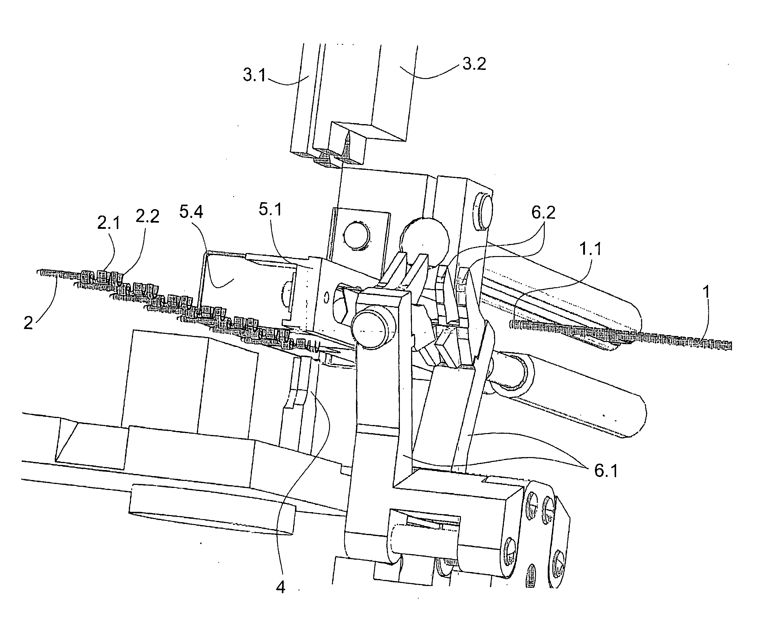
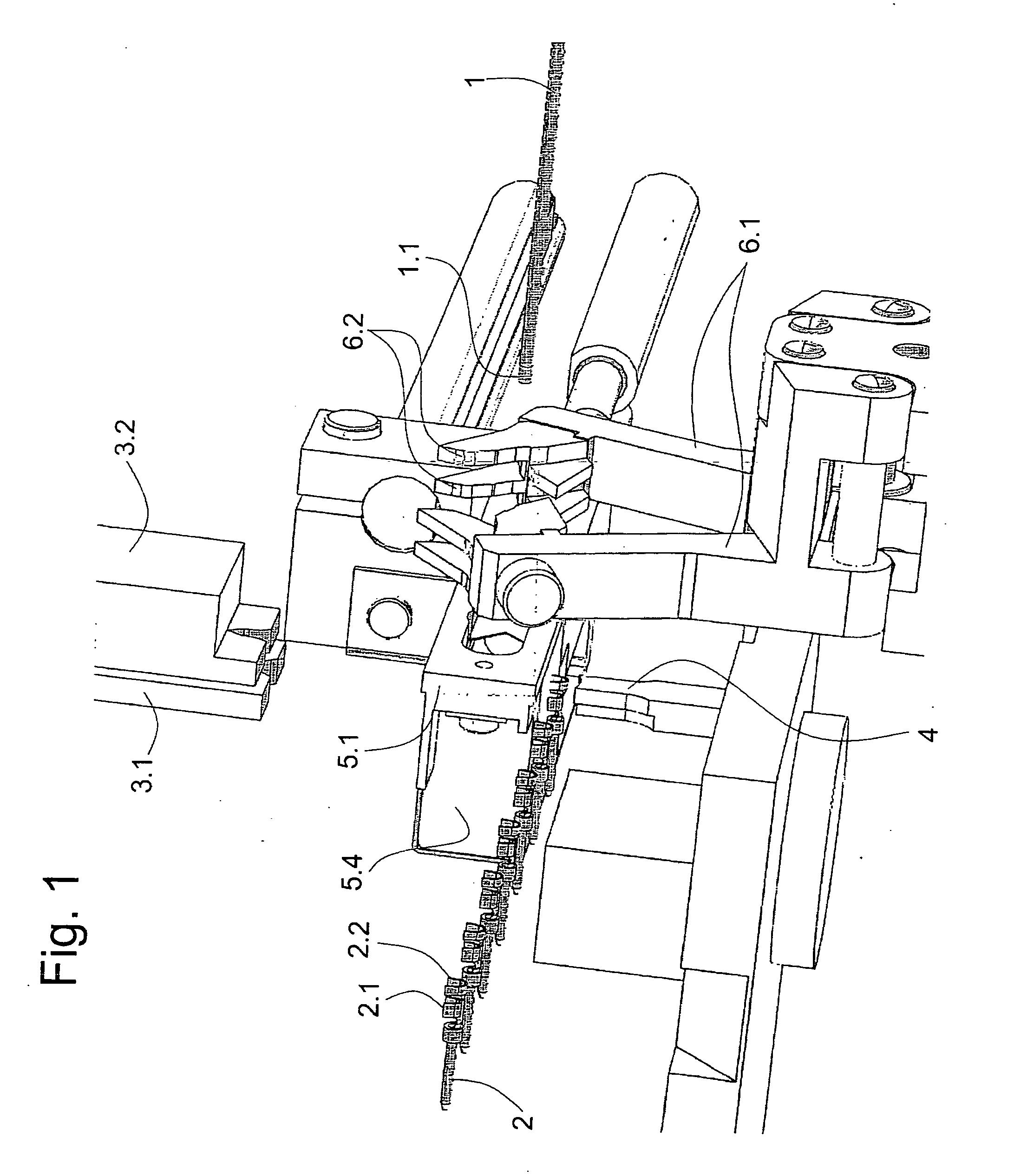
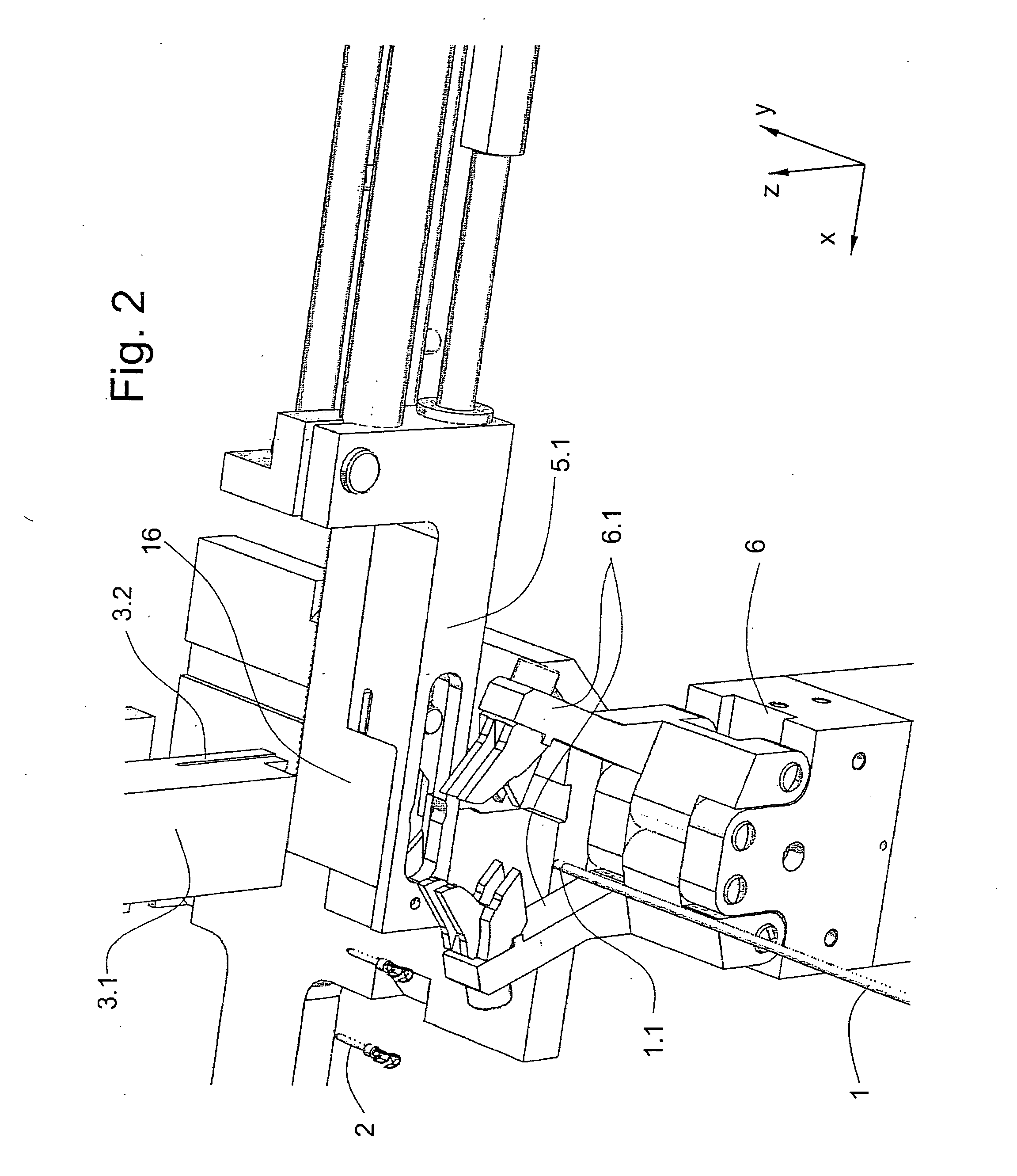
[0015]FIG. 1 shows the main parts of a unit according to the present invention for processing a wire-end. For creation of a crimped connection between a wire-end 1.1 of a wire 1 and a crimp contact 2, a crimp punch 3.1 for a conductor crimp 2.1 and a crimp punch 3.2 for an insulation crimp 2.2 are needed, the crimp punches 3.1, 3.2 pressing the conductor crimp 2.1 and the insulation crimp 2.2 respectively against an anvil 4 and plastically deforming lugs of the conductor crimp 2.1 and the insulating crimp 2.2 respectively. The wire 1 is advanced as far as a cutting head 5.1 and held by a gripper pair 6.1 by means of mutually interlocking fingers 6.2. The cutting head 5.1 cuts off the leading wire-end 1.1 and strips the wire-end 1.1 of insulation as far as necessary for the conductor crimp 2.1. To create the crimp connection, the crimp punches 3.1, 3.2 are lowered in a vertical direction, the gripper pair 6.1 and the wire-end 1.1 being lowered with them. As shown diagrammatically, th...


PUM

PropertyMeasurementUnit
Contentaaaaaaaaaa

Abstract

A wire processing unit has a crimp head moved in a “z” direction by an eccentric drive and a crimping tool arranged on the crimp head moves with it. The crimp head also moves a pin connected to a lowering unit that has a C-shaped bracket on which the gripper unit is arranged. When a crimping punch moves, the gripper unit is moved with it, and the wire-end held by a gripper pair is inserted into an upwardly-open conductor crimp and an insulation crimp respectively. A cutting head of a cutting unit cuts off the leading wire-end, removes the insulation, and separates contacts with defective crimp fastening from the wire-end.

Description

BACKGROUND OF THE INVENTION [0001] The present invention relates to a device for processing a wire, comprising components for holding and cutting the wire. [0002] The European patent specification EP 0 989 637 A1 shows a processing unit for processing wire-ends. The processing unit cuts the leading ends off wires and fastens contacts onto the stripped wire-ends by means of crimping. The processing unit comprises arranged in a machine frame including a gripper unit, a cutting head, an ejector, an adjusting device, and a crimping device. The wire-end of a wire is advanced manually as far as a processing area, with a trigger detecting the correct position of the wire-end. As soon as the trigger detects the wire-end, the processing operation begins, defectively fastened contacts being separated from the wire by means of a contact cutter. The cutting head comprises a separating cutter to cut the leading wire-end off the wire and a stripping cutter to strip the wire-end of insulation. [00...

Claims


Application Information

Patent Timeline
IPC IPC(8): B23D33/00B26D3/16B23D36/00H01B13/00H01L21/60H01R43/05H01R43/052
CPCH01L24/78Y10T29/49192H01L2924/01033H01L2924/01082H01L2924/3025H01R43/05H01R43/052H01L2924/01005H01L2924/01006H01L2924/00014H01L2224/78Y10T29/514Y10T29/53235Y10T29/5187Y10T29/53226Y10T29/5193Y10T29/53243Y10T29/53213Y10T29/53217Y10T29/532H01L2224/48Y10T83/8772Y10T83/9447H01L2224/45099H01B13/00B26D3/16
Inventor RUCHTI, NICOLAS
Owner KOMAX HOLDING
Why Eureka
Try Eureka