Rotary fluid machine

a fluid machine and rotary technology, applied in the direction of machines/engines, combination engines, liquid fuel engines, etc., can solve the problems of abnormal wear or leakage, lubricating oil undetected contamination of working medium, and reducing the durability of seals, etc., to suppress the increase of leakage and abnormal wear.

Inactive Publication Date: 2005-04-28
HONDA MOTOR CO LTD
View PDF2 Cites 6 Cited by
  • Summary
  • Abstract
  • Description
  • Claims
  • Application Information

AI Technical Summary

Benefits of technology

[0007] The present invention has been achieved under the above-mentioned circumstances, and an object thereof is to suppress the increase in leakage and the occurrence of abnormal wear by minimizing the variation, due to thermal expansion, of the clearance between the sliding surfaces of a fixed shaft and a rotating shaft of a rotary fluid machine.
[0009] In accordance with this arrangement, since at least the inner periphery of the rotating shaft, which is provided integrally with the rotor and is rotatably supported by the fixed shaft with the sliding surfaces thereof in hermetic contact, is formed by shrink-fitting the outer sleeve, which is made of metal, around the outer periphery of the inner sleeve, which is made of a material having a lower coefficient of thermal expansion than that of metal, even when the rotating shaft attempts to expand due to the high temperature gas-phase working medium, thermal expansion of the outer sleeve, which is made of metal and is shrink-fitted around the outer periphery of the inner sleeve, is suppressed by residual tensile stress of the outer sleeve, and intimate contact between the outer sleeve and the inner sleeve is maintained. As a result, the overall thermal expansion of the rotating shaft depends on the thermal expansion of the inner sleeve, which is made of a material having a low coefficient of thermal expansion, and change in the internal diameter of the rotating shaft is therefore suppressed, thereby stabilizing the clearance between the sliding surfaces of the rotating shaft and the fixed shaft.
[0011] In accordance with this arrangement, since at least the outer periphery of the fixed shaft, which is fixed to the casing and rotatably supports the rotating shaft with the sliding surfaces thereof in hermetic contact, is formed by shrink-fitting the outer sleeve, which is made of metal, around the outer periphery of the inner sleeve, which is made of a material having a lower coefficient of thermal expansion than that of metal, even when the fixed shaft attempts to expand due to the high temperature gas-phase working medium, thermal expansion of the outer sleeve, which is made of metal and is shrink-fitted around the outer periphery of the inner sleeve, is suppressed by residual tensile stress of the outer sleeve, and intimate contact between the outer sleeve and the inner sleeve is maintained. As a result, the overall thermal expansion of the fixed shaft depends on the thermal expansion of the inner sleeve, which is made of a material having a low coefficient of thermal expansion, and change in the external diameter of the fixed shaft is therefore suppressed, thereby stabilizing the clearance between the sliding surfaces of the rotating shaft and the fixed shaft.
[0013] In accordance with this arrangement, since at least the inner periphery of the rotating shaft, which is provided integrally with the rotor and is rotatably supported by the fixed shaft with the sliding surfaces thereof in hermetic contact, is formed by shrink-fitting the outer sleeve, which is made of a metal, around the outer periphery of the inner sleeve, which is made of a material having a lower coefficient of thermal expansion than that of metal, even when the rotating shaft attempts to expand due to the high temperature gas-phase working medium, thermal expansion of the outer sleeve, which is made of metal and is shrink-fitted around the outer periphery of the inner sleeve, is suppressed by residual tensile stress of the outer sleeve, and intimate contact between the outer sleeve and the inner sleeve is maintained. Furthermore, since at least the outer periphery of the fixed shaft, which is fixed to the casing and rotatably supports the rotating shaft with the sliding surfaces thereof in hermetic contact, is formed by shrink-fitting the outer sleeve, which is made of metal, around the outer periphery of the inner sleeve, which is made of a material having a lower coefficient of thermal expansion than that of metal, even when the fixed shaft attempts to expand due to the high temperature gas-phase working medium, thermal expansion of the outer sleeve, which is made of metal and is shrink-fitted around the outer periphery of the inner sleeve, is suppressed by residual tensile stress of the outer sleeve, and intimate contact between the outer sleeve and the inner sleeve is maintained. As a result, the overall thermal expansion of the rotating shaft depends on the thermal expansion of the inner sleeve, which is made of a material having a low coefficient of thermal expansion, and change in the internal diameter of the rotating shaft is suppressed; in addition, the overall thermal expansion of the fixed shaft depends on the thermal expansion of the inner sleeve, which is made of a material having a low coefficient of thermal expansion, and change in the external diameter of the fixed shaft is suppressed, thereby synergistically stabilizing the clearance between the sliding surfaces of the rotating shaft and the fixed shaft.
[0015] In accordance with this arrangement, since the outer sleeve of the fixed shaft, the outer sleeve being made of metal, is subjected to coating with a low friction material that is difficult to apply to a material such as ceramic, which has a low coefficient of thermal expansion, the frictional resistance of the sliding surfaces of the fixed shaft and the rotating shaft can be further reduced.

Problems solved by technology

If an attempt is made to ensure the sealing characteristics of the rotary valve by means of a seal, there is the problem of a decrease in the durability of the seal, which is exposed to a high temperature gas-phase working medium, and if an attempt is made to ensure the sealing characteristics by means of a lubricating oil, the lubricating oil undesirably contaminates the working medium.
However, since the difference in temperature of the rotary valve between when it is hot and when it is cold is extremely large, the clearance varies due to thermal expansion, and there is a possibility that abnormal wear or leakage might occur.
That is, when a high temperature gas-phase working medium is supplied to the rotary valve through the interior of the fixed shaft when cold, the fixed shaft, which is on the inside, thermally expands first, and the rotating shaft, which is on the outside, thermally expands after a time lag, the clearance therebetween decreases, and abnormal wear is caused due to the contact.
In order to avoid this problem, the use of a material such as ceramic that has a small coefficient of thermal expansion for both the fixed shaft and the rotating shaft can be considered, but the sliding surfaces of materials of the same type have poor sliding characteristics, and there is a possibility that the friction might increase or that seizing might occur.
Furthermore, when an attempt is made to apply a low friction material in order to improve the sliding characteristics, there is the problem that it is difficult to coat ceramic.

Method used


Image

  • Rotary fluid machine
  • Rotary fluid machine
  • Rotary fluid machine

Examples


first embodiment

[0040] the present invention is explained below with reference to FIG. 1 to FIG. 21D.

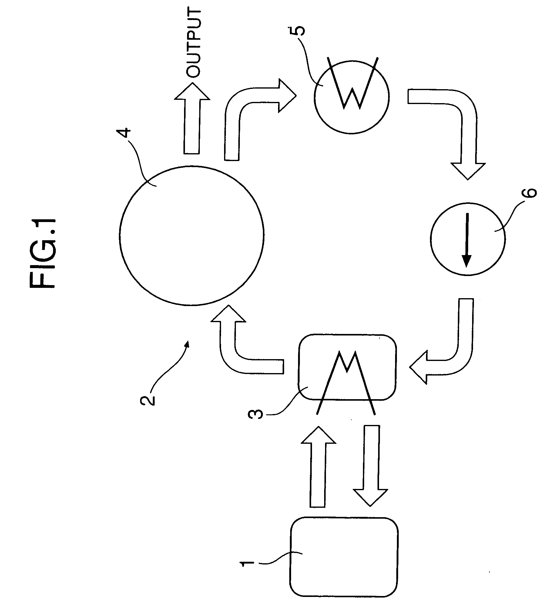
[0041] In FIG. 1, a waste heat recovery system 2 for an internal combustion engine 1 includes an evaporator 3 that generates high temperature, high pressure steam by vaporizing a high pressure liquid (e.g. water) using as a heat source the waste heat (e.g. exhaust gas) of the internal combustion engine 1, an expander 4 that generates an output by expansion of the steam, a condenser 5 that liquefies steam having decreased temperature and pressure as a result of conversion of the pressure energy into mechanical energy in the expander 4, and a supply pump 6 that pressurizes the liquid (e.g. water) from the condenser 5 and resupplies it to the evaporator 3.

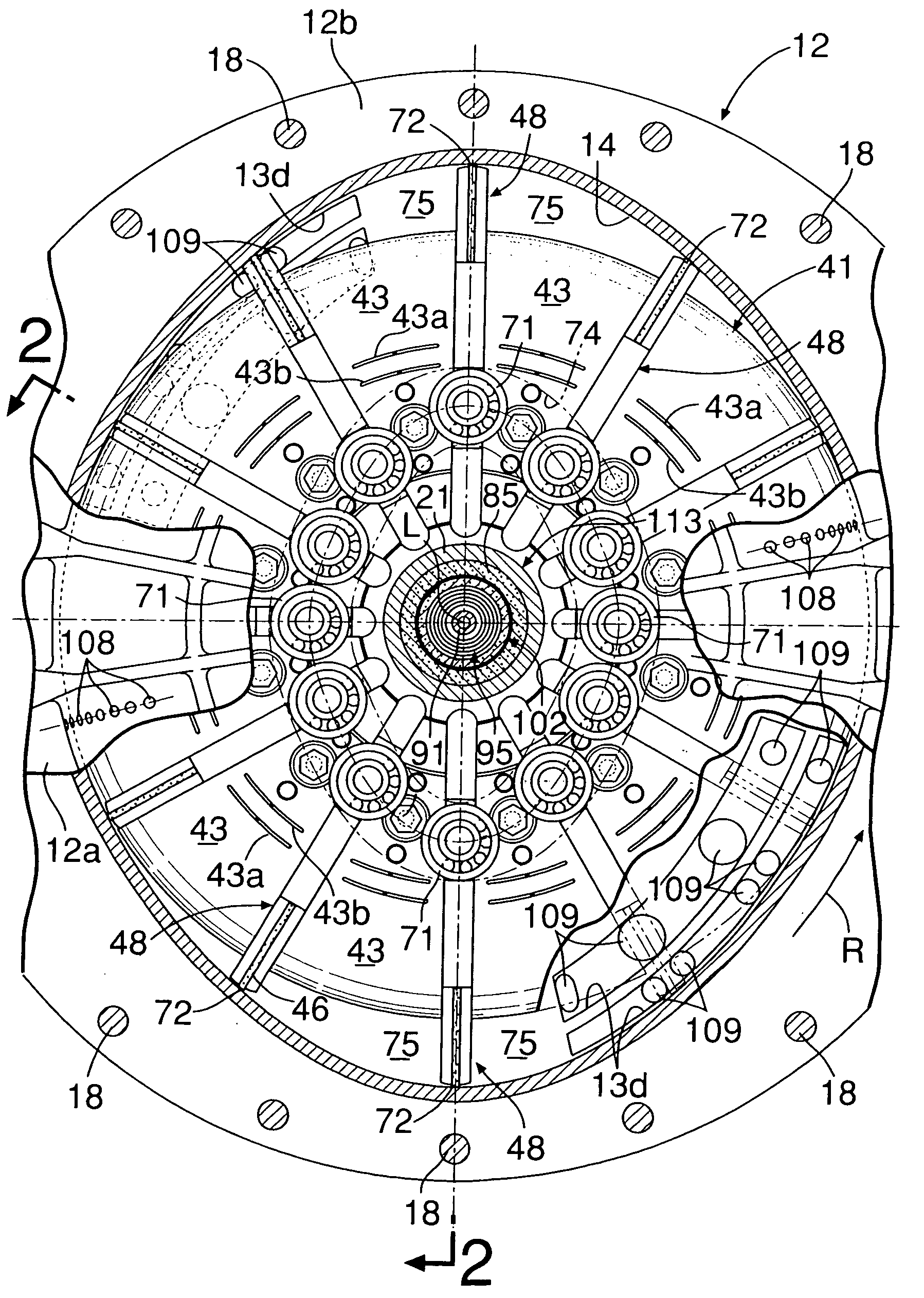
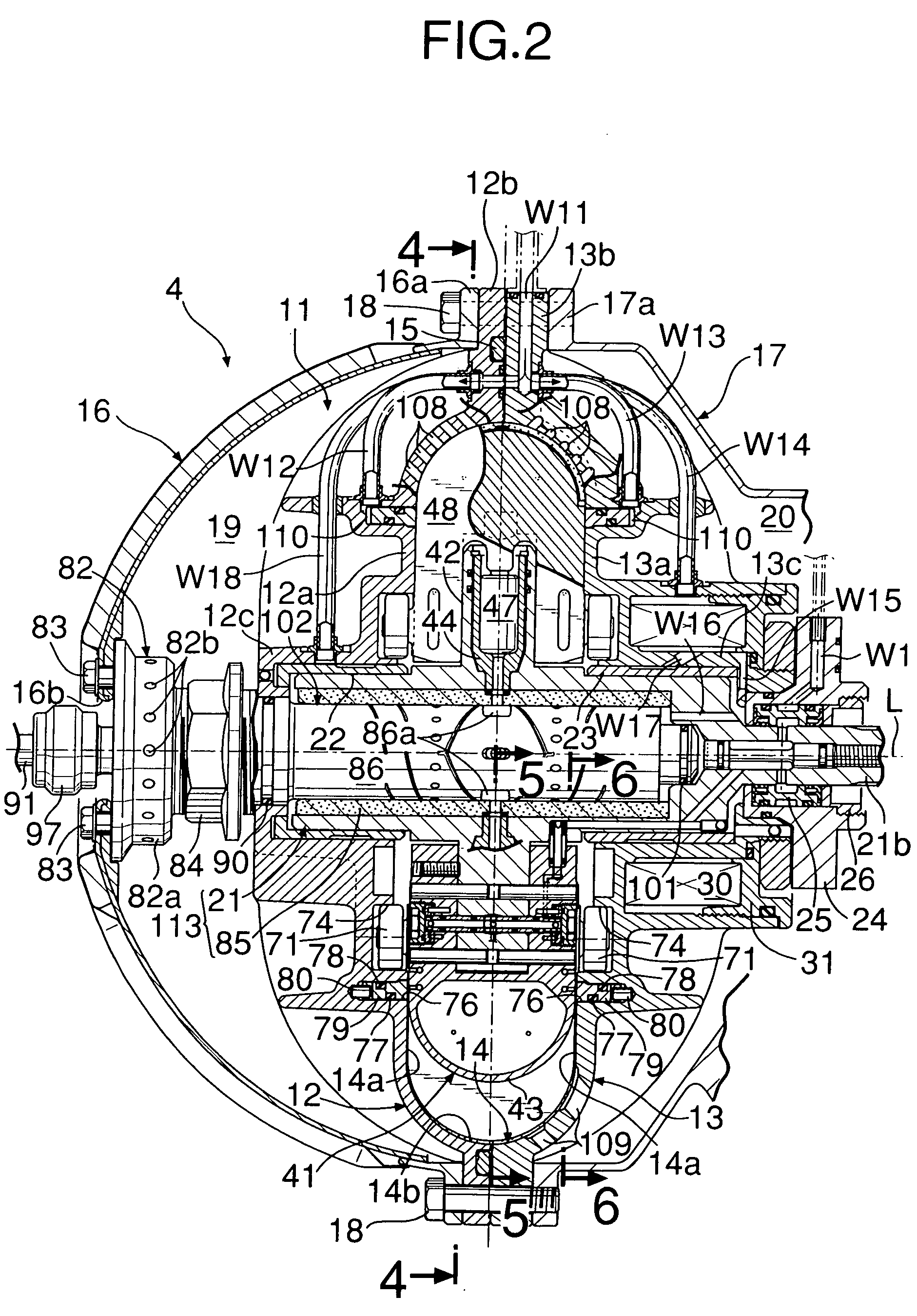
[0042] As shown in FIG. 2 and FIG. 3, a casing 11 of the expander 4 is formed from first and second casing halves 12 and 13, which are made of metal. The first and second casing halves 12 and 13 are formed from main body portions 12a and 13a, which i...


PUM


Abstract

A rotary fluid machine is provided that includes a rotor rotatably housed within a casing, a hollow rotating shaft (113) that rotates integrally with the rotor, and a fixed shaft (102) that is relatively rotatably fitted into the inner periphery of the rotating shaft (113); in which the rotating shaft (113) is formed by shrink-fitting an outer sleeve (21) made of metal around the outer periphery of an inner sleeve (85) made of ceramic, etc. having a lower coefficient of thermal expansion than that of metal, and the fixed shaft (102) is formed by shrink-fitting an outer sleeve (88) made of metal around the outer periphery of an inner sleeve (87) made of ceramic, etc. having a lower coefficient of thermal expansion than that of metal. Since thermal expansion of the outer sleeves (21, 88) fitted around the outer peripheries of the inner sleeves (85, 87) is suppressed due to residual tensile stress of the outer sleeves (21, 88), intimate contact between the outer sleeves (21, 88) and the inner sleeves (85, 87) can be maintained.

Description

FIELD OF THE INVENTION [0001] The present invention relates to a rotary fluid machine for interconverting the pressure energy of a gas-phase working medium and the rotational energy of a rotor. BACKGROUND ART [0002] A rotary fluid machine disclosed in Japanese Patent Application Laid-open No. 2000-320543 is equipped with a vane piston unit in which a vane and a piston are combined; the piston, which is slidably fitted in a cylinder provided radially in a rotor, interconverts the pressure energy of a gas-phase working medium and the rotational energy of the rotor via a power conversion device comprising an annular channel and a roller, and the vane, which is radially and slidably supported in the rotor, interconverts the pressure energy of the gas-phase working medium and the rotational energy of the rotor. [0003] In such a rotary fluid machine, a rotary valve for supplying and discharging a high temperature gas-phase working medium is formed between the outer peripheral face of a fi...

Claims


Application Information

Patent Timeline
Patent Type & Authority Applications(United States)
IPC IPC(8): F01B1/06F01B13/06F01L15/08F01C1/344F01C11/00F01C19/08F01C21/18F01K7/00F01K23/06F02G5/00F04C18/344
CPCF01B1/0603F01B13/061F01B13/068F01C1/3446F01C11/006Y02T10/166F02G5/00F04C2230/60F04C2240/60F04C2240/605F05C2203/08F01C21/18Y02T10/12
Inventor KIMURA, YASUNARIENDOH, TSUNEOICHIKAWA, HIROSHITAKAHASHI, TSUTOMU
Owner HONDA MOTOR CO LTD
Why Eureka
Try Eureka