
Hybrid circuit

a hybrid circuit and circuit technology, applied in the direction of battery/fuel cell control arrangement, electric devices, transportation and packaging, etc., can solve the problem of more damage to battery functions, and achieve the effect of preventing an increase in the layout area and the occurrence of short circuits

Active Publication Date: 2015-12-08
YAZAKI CORP
View PDF16 Cites 1 Cited by
  • Summary
  • Abstract
  • Description
  • Claims
  • Application Information

AI Technical Summary

Benefits of technology

The present invention aims to provide a hybrid circuit that can prevent an increase in layout area and short circuits while having versatile high-voltage and low-voltage circuits. The high-voltage circuit is mounted on the hybrid integrated circuit, which prevents short circuits caused by foreign particles. The control unit for the high-voltage circuit, as well as the high-voltage circuit and connector for high-voltage system, are also mounted on the hybrid integrated circuit. This makes it easy to change the specifications of the high-voltage circuit without changing the entire hybrid circuit, which saves time and effort during design changes. The hybrid circuit has a compact structure that allows for the arrangement of the connector for high-voltage system without increasing the distance between the low-voltage substrate and the hybrid integrated circuit, resulting in downsizing of the entire hybrid circuit.

Problems solved by technology

This means that, an abnormal electrical discharge creates more damage to battery functions of a lithium-ion battery than to a lead-acid battery, and a lithium-ion battery generates more heat in itself and the wiring thereof than a lead-acid battery when abnormal electrical discharge happens.

Method used


Image

  • Hybrid circuit
  • Hybrid circuit
  • Hybrid circuit

Examples


Embodiment Construction

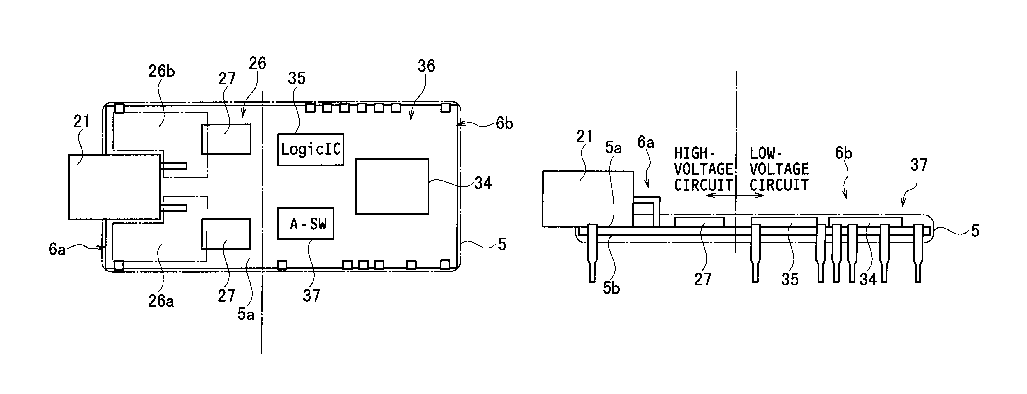
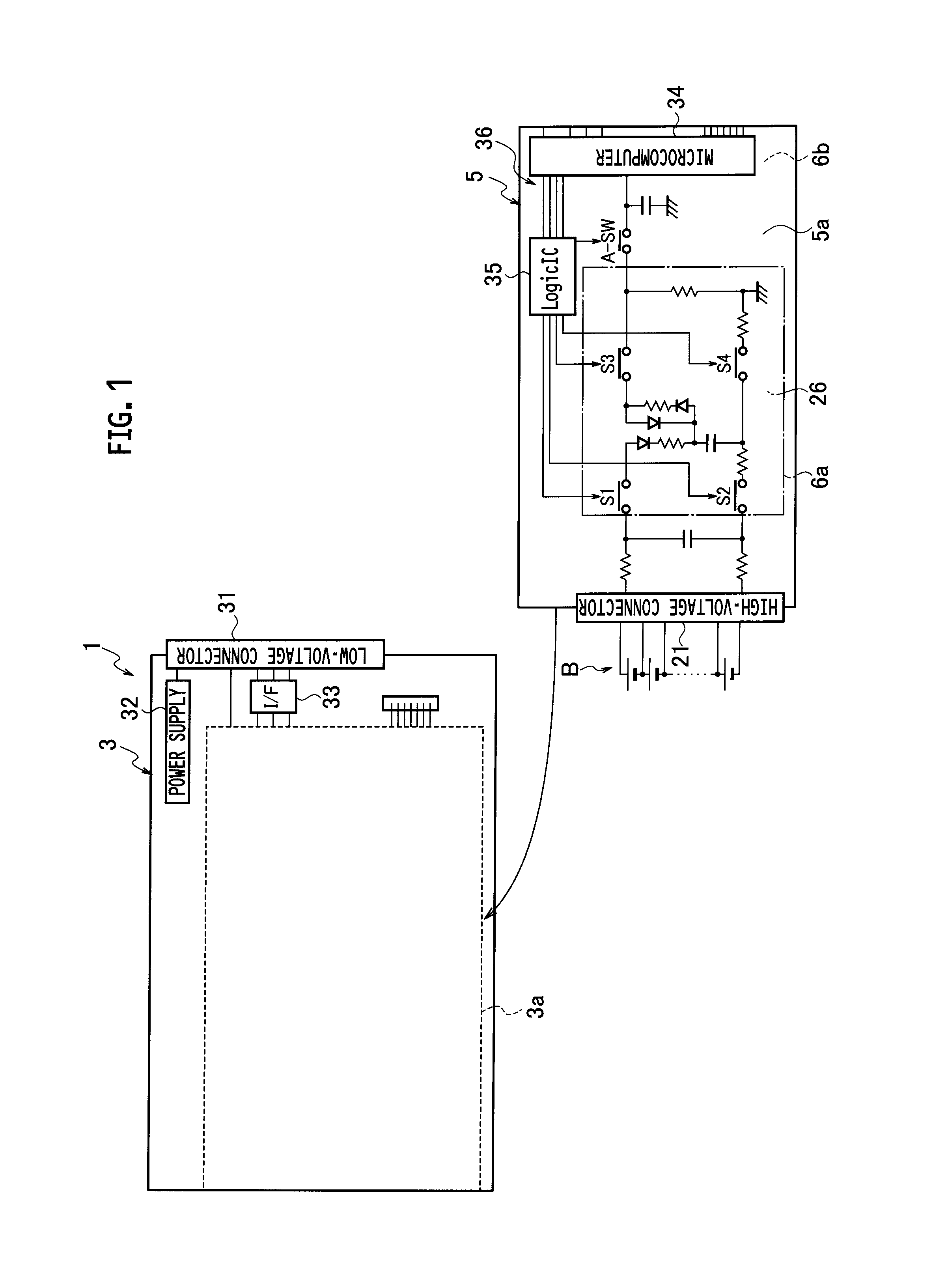
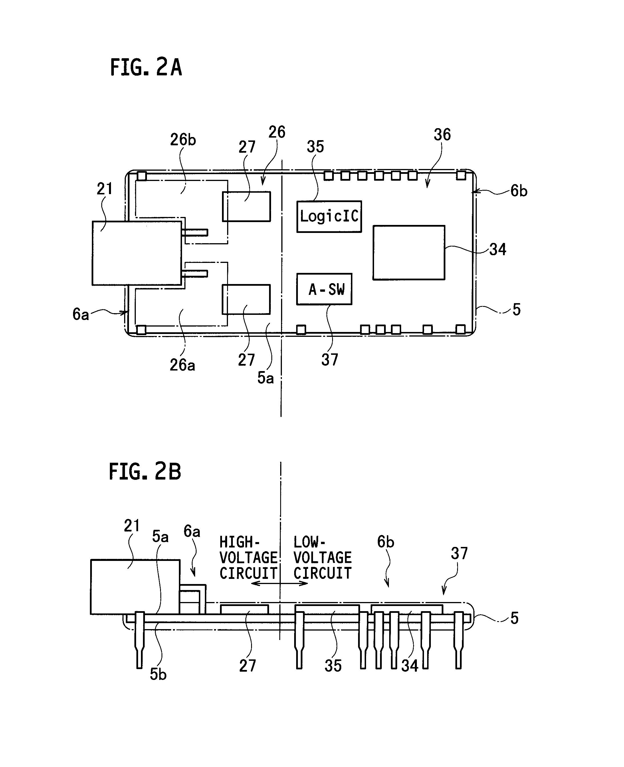
[0028]An embodiment of the present invention will be explained below with reference to the drawings.

[0029]First, a mounting structure of a hybrid circuit according to the embodiment will be described with reference to FIGS. 1, 2A and 2B.

[0030]As illustrated in FIG. 1, a hybrid circuit 1 according to the embodiment is provided in a voltmeter device which measures an output voltage of a lithium-ion battery B (an external high-voltage element) made of cells, and includes a low-voltage substrate 3 and a substrate-shaped hybrid integrated circuit 5.

[0031]Mounted on the low-voltage substrate 3 are, for example, a low-voltage connector 31 (a connector for a low-voltage system) to be connected to an ECU (electronic control unit, equivalent to an external low-voltage element) installed in a vehicle (not illustrated), a power supply 32 which supplies electricity to the low-voltage connector 31, and an interface 33 connected to the low-voltage connector 31.

[0032]In the low-voltage substrate 3,...


PUM


Abstract

In a hybrid circuit including a high-voltage circuit and a low-voltage circuit having different power supply voltages from each other, a voltmeter serving as a high-voltage circuit, a high-voltage connector for connecting the voltmeter and the lithium ion battery, the control unit which is a part of the low-voltage circuit and performs switching control to turn on / off internal switches of the voltmeter are mounted on a hybrid integrated circuit. Then, the hybrid integrated circuit is stacked on top of a hybrid integrated circuit mounting area of a low-voltage substrate on which the rest of the low-voltage circuit is mounted.

Description

BACKGROUND OF THE INVENTION[0001]1. Field of the Invention[0002]The present invention relates to a hybrid circuit including a high-voltage circuit and a low-voltage circuit which have different power-supply voltages from each other.[0003]2. Description of the Related Art[0004]As a hybrid circuit including a high-voltage circuit and a low-voltage circuit having different power-supply voltages from each other, hybrid circuits described in JP 11-176479 A (Patent Literature 1) and JP 2006-009687 A (Patent Literature 2) have been proposed. According to the Patent Literature 1 and the Patent Literature 2, a high-voltage circuit and a low-voltage circuit are mounted on different substrates, respectively, and these substrates are located by being stacked in a hierarchy manner, thus suppressing an increase in a layout area of the substrates.SUMMARY OF THE INVENTION[0005]Examples of fields where a hybrid circuit having a high-voltage circuit and a low-voltage circuit is used include vehicles ...

Claims


Application Information

Patent Timeline
Patent Type & Authority Patents(United States)
IPC IPC(8): H02J1/00H02J3/30B60L3/00B60L11/18
CPCB60L3/0046B60L11/1859Y02T10/7005Y02T10/705Y02T10/7011Y10T307/406B60L58/14Y02T10/70
Inventor KAWAMURA, YOSHIHIRO
Owner YAZAKI CORP
Learn More