Brake for a lift

Inactive Publication Date: 2005-04-28
INVENTIO AG
View PDF15 Cites 21 Cited by
  • Summary
  • Abstract
  • Description
  • Claims
  • Application Information

AI Technical Summary

Benefits of technology

[0006] The present invention overcomes the disadvantages of the prior art, and is in the

Problems solved by technology

A disadvantage of such known equipment resides in the fact that the brake produces different braking moments in the case of normal operation and in the case of failure of a brake half.
In the known brake one brake half generates the necessary braking moment; the two brake halves together produce twice the braking moment, which in the case of normal operat

Method used


Image

  • Brake for a lift
  • Brake for a lift
  • Brake for a lift

Examples


Example

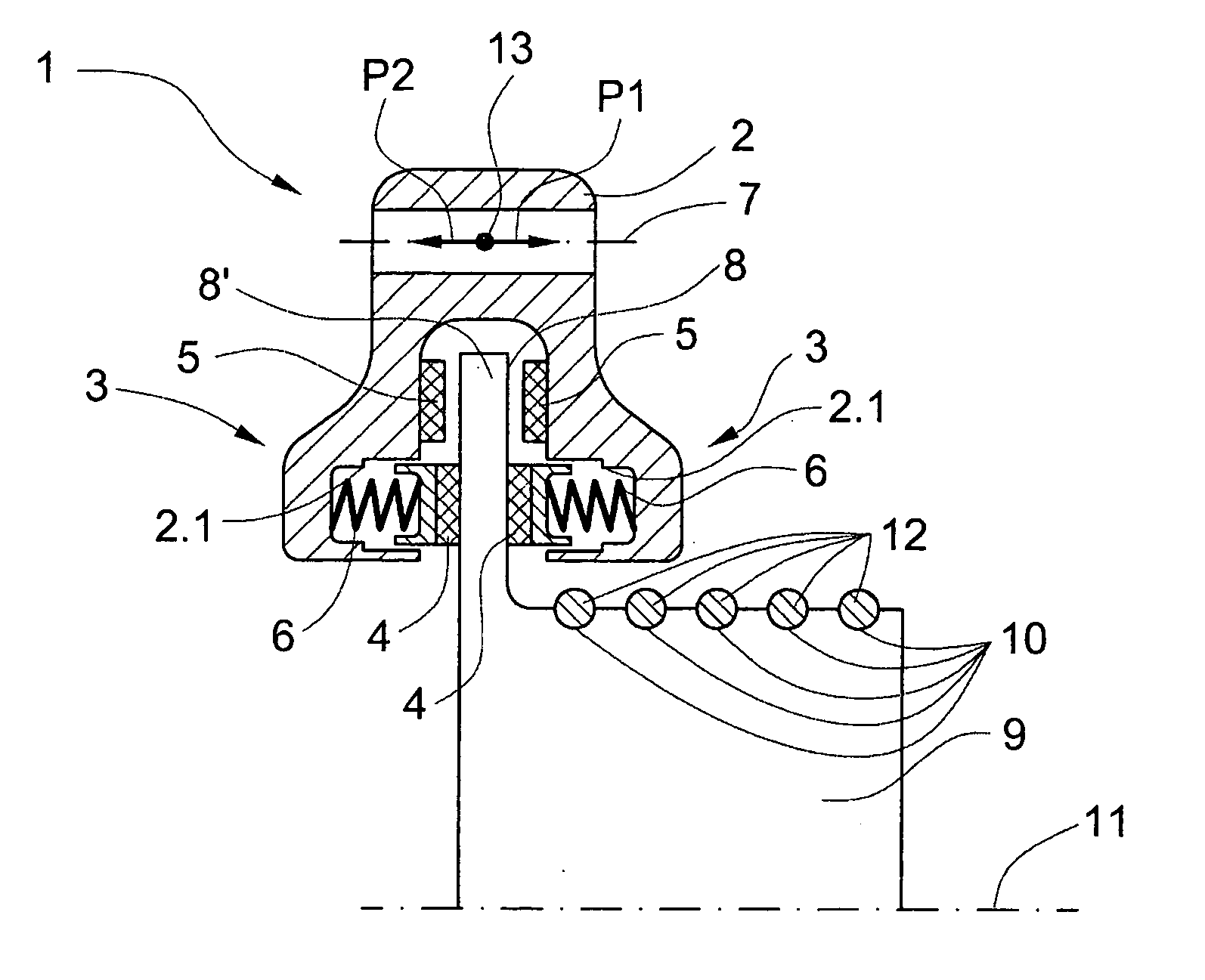
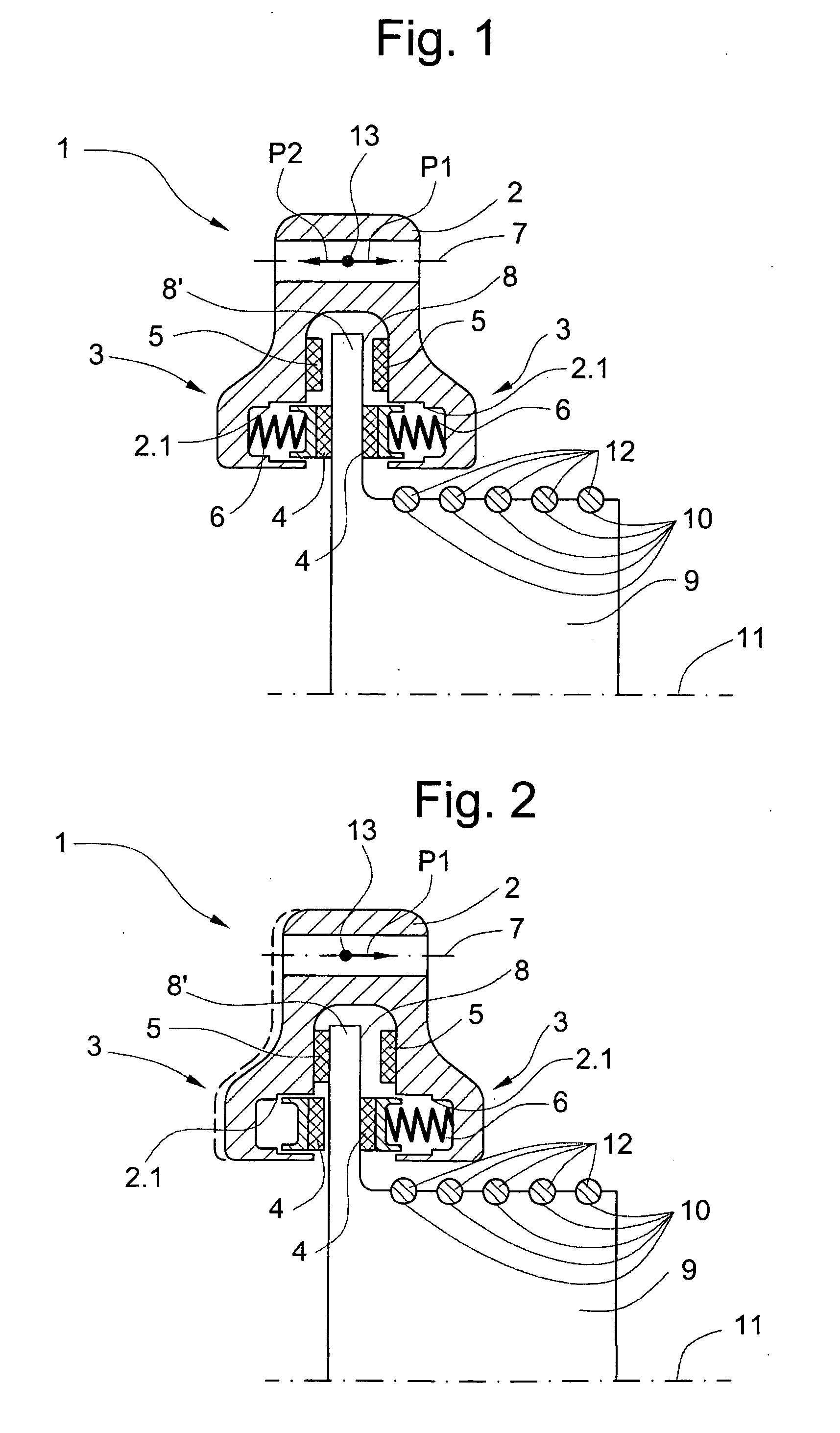
[0015]FIG. 1 is a schematic illustration of the brake 1 according to the invention in normal operation. The brake 1 comprises a housing 2 which is U-shaped in cross-section, wherein a limb of the U corresponds to a brake half 3. The brake halves 3 are of identical construction. An active brake lining 4 and at least one additional or passive brake lining 5 are provided for each brake half 3. In a variant of embodiment the additional brake lining 5 can, as explained further below, be omitted. Each additional or passive brake lining 5 is arranged at an inner side of the limbs of housing 2. The active brake lining 4 is loaded by the spring force of a compression spring 6. Not illustrated is an actuator which is explained further below and which in the activated state opposes the spring force. The housing is mounted to be floating along a first axis 7. It is to be noted that the additional linings 5 are shown in both FIGS. 1 and 2 displaced from their actual locations adjacent the active...


PUM


Abstract

A self-centering brake for a lift provides for the same braking moment in the case of normal operation and in the case of failure of a brake half. The brake consists of a housing which is U-shaped in cross-section, wherein a limb of the U corresponds with a brake half. The brake halves are of identical construction. An active brake lining and a passive brake lining are provided for each brake half. The active brake lining is loaded by a spring force of a compression spring. In the case of failure of a brake half the passive brake lining takes over the function of the active brake lining.

Description

[0001] The invention relates to a brake for a lift, which brake consists of two brake halves, wherein a compression spring for activation of the brake and an actuator for release of the brake are provided for each brake half and wherein the compression spring and actuator act on at least one active brake lining, which produces a braking force at a brake surface when the actuator is deactivated. BACKGROUND OF THE INVENTION [0002] A brake device for a hoist frame drivable by means of a linear motor has become known from patent specification DE 41 06 595, wherein load cells produce a releasing signal. Brakes arranged at the hoist frame embrace the guide rails arranged in the conveying shaft, wherein a brake is provided for each guide rail. The brake has a brake shoe for each limb side of the guide rail. Actuating elements produce, for each brake shoe, braking forces on the guide rail by means of the brake shoe, wherein the action of a spring activates the brake and a hydraulic cylinder...

Claims


Application Information

Patent Timeline
IPC IPC(8): B66B5/02B66B1/32B66B5/18B66B11/08B66D5/14B66D5/30F16D55/00F16D55/224F16D63/00F16D65/02F16D65/18
CPCB66B5/18B66D5/30B66D5/14
Inventor FISCHER, DANIEL
Owner INVENTIO AG
Why Eureka
Try Eureka