Explosively driven radio frequency pulse generating apparatus

a radio frequency pulse and generator technology, applied in pulse generators, electrical devices, pulse train generators, etc., can solve the problems of rf pulses of such size that can damage computers and digital electronic systems, waste rf energy available in oscillatory circuits, and can not be optimal for all frequencies. achieve the effect of high voltage impulses

Inactive Publication Date: 2005-04-28
KEKEZ MLADEN MARKO +1
View PDF10 Cites 4 Cited by
  • Summary
  • Abstract
  • Description
  • Claims
  • Application Information

AI Technical Summary

Benefits of technology

[0016] The present invention uses an MCG to create high frequency pulses of short duration. The physical device of the present invention comprises a helical MCG, which generates high voltage impulses due to the compressed magnetic flux inside the MCG. The helix of the MCG with its inner conducting tube has the function of an RF oscillatory circuit. The vortex wake arising from the detonation and combustion processes assumes the function of a quarter-wave trap / antenna. If the MCG is in high velocity flight, a bow-shaped shock wave, followed by a second shock front will be established around the head of the MCG. These shock waves provide the primary antenna. When the MCG is stationary, the physical dimension of a coupling capacitor provided in the oscillatory circuit will produce the primary antenna. Alternatively, two MCG's can be joined head to head and ignited at the same time to produce the primary and quarter-wave trap antennas. The primary antenna and the quarter-wave trap antenna are capable of supplying spherical transverse electromagnetic (TEM) waves.

Problems solved by technology

If the antennas are absent, the RF energy available in the oscillatory circuit is wasted.
The antenna can have any form, however not all forms are optimal for all frequencies.
It has been observed that an RF pulse of such size is capable of causing damage to computers and digital electronic systems.

Method used


Image

  • Explosively driven radio frequency pulse generating apparatus
  • Explosively driven radio frequency pulse generating apparatus
  • Explosively driven radio frequency pulse generating apparatus

Examples


experiment 1

[0055] The helix was wound on a plexiglass tube with a 7.5 cm diameter and 35 cm length at a rate of 7 turns per 10 cm. The diameter of the inner conducting tube was 5 cm. The separation between the turns was 4.5 mm and the cross-section of the copper wire used was 3.1 mm*0.75 mm. The helix was energized by the impulse generator with CG=1.14 nF and CA charged to V=112 kV.

[0056] In accordance with the teachings of the co-pending application (by M. M. Kekez and D. D. Kekez, “Radio Frequency Pulse Generating Apparatus”) the antennas / λ / 4 trap were set for a frequency emission of 44 MHz. An additional antenna (66 in FIG. 3) acts as the capacitive load Its size was optimized until the output radiation reached a maximum value.

[0057] For a voltage above 70 kV, visible corona type electrical discharges between the turns of the helix were observed. These discharges produced oscillations in the current waveform, as shown in FIG. 8, Frame A. On the whole, the helix behaves rather like a conve...

experiment 2

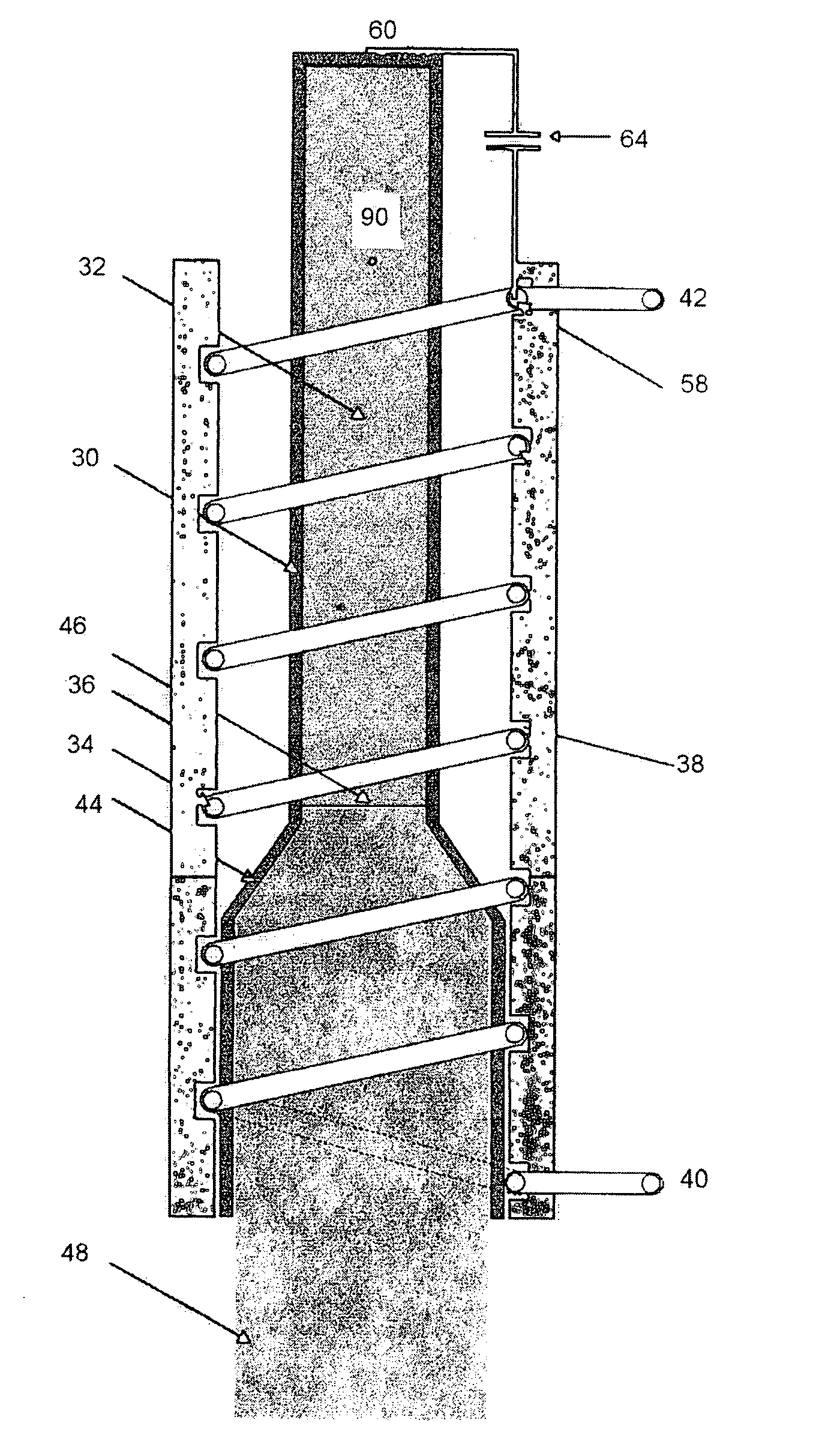
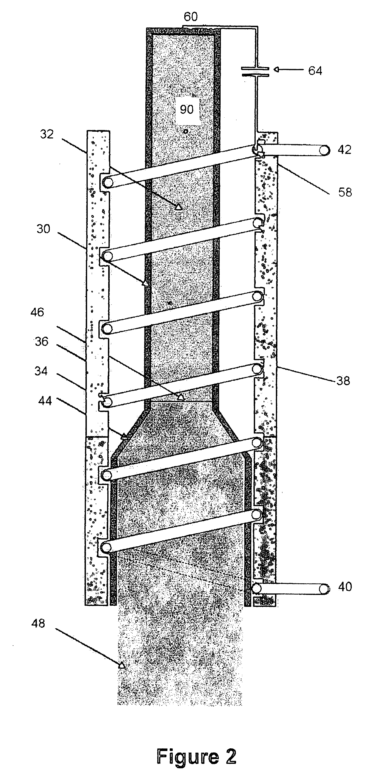
[0058] Keeping the experimental conditions of FIG. 8, FIG. 9 was obtained by converting the corona discharges into spark discharges. There are many methods of forcing the corona discharges to be transformed into the single spark channel that bridges the turns of a helix in the slot assumed present in FIG. 2. One method is to remove or weaken the insulation at the point where the spark channel occurs. Alternatively, the separation between turns can be decreased by flattening the wire at the points resting in the longitudinal direction in the slot of the helix.

[0059] For the experimental conditions of FIG. 8, the power radiated was seen to rise to 35 MW at the same frequency of 44 MHz. For a pulse duration of 60 ns, the total energy of the radiation is 2.8 J. This represents a six-fold increase in the emitted energy over the configuration of Experiment 1. The energy stored in the impulse generator remained the same (7.17 J.). An FFT of the signal 78 shows two frequency peaks: 44 and ...


PUM


Abstract

A device for generating an intense radio frequency pulse through use of a helical Magneto-Cumulative Generator (MCG). The MCG provides a chemical explosion and acts as a converter to transform the chemical/mechanical energy into an electrical energy impulse. Due to the detonation/combustion process, a vortex wake is produced which assumes the role of a quarter-wave trap/antenna. If the MCG is in high velocity flight, a bow-shaped shockwave, followed by a second shock front, is established around the head of the MCG, becoming a second antenna. Without flight, two MCG's are placed head-to-head so that the vortex wakes emit in opposite directions. Since the explosion destroys the MCG, a model is created to perform multiple tests of the ability of an MCG to act as an RF device.

Description

BACKGROUND OF THE INVENTION [0001] 1. Field of the Invention [0002] The invention relates to a device that generates an intense radio frequency (RF) pulse. The primary source of energy is a chemical explosion, provided by a magneto-cumulative generator (MCG). The apparatus transforms the electrical pulse of the MCG into a powerful RF pulse. [0003] 2. Background Information [0004] Attempts to create a device for generating high voltage pulses of short duration have resulted in several patents. One of the first patents on this topic was issued on Jun. 5, 1951 to R. L. Alty as U.S. Pat. No. 2,555,305, which teaches the use of a transmitter as a load, driven by a pulse generating circuit consisting of an inductor, a capacitor and a switch. Several other patents have issued since Alty's, with modifications on his basic idea. One such patent is U.S. Pat. No. 3,579,111 issued to Lexington et al on May 18, 1971. This more recent patent uses a tank circuit and a charging inductor to achieve ...

Claims


Application Information

Patent Timeline
Patent Type & Authority Applications(United States)
IPC IPC(8): H02N11/00
CPCH02N11/004
Inventor KEKEZ, MLADEN MARKOKEKEZ, DANIEL DAVID
Owner KEKEZ MLADEN MARKO
Why Eureka
Try Eureka