Spoke permanent magnet rotors for electrical machines and methods of manufacturing same

a permanent magnet rotor and rotor body technology, applied in the field of electric machines, can solve the problems of complex construction required to reduce, and the difficulty in retaining permanent magnets and pole pieces, and achieve the effect of reducing costs and improving performan

Active Publication Date: 2005-04-28
REGAL BELOIT AMERICA
View PDF46 Cites 47 Cited by
  • Summary
  • Abstract
  • Description
  • Claims
  • Application Information

AI Technical Summary

Benefits of technology

[0006] The invention provides spoke permanent magnet rotors that provide enhanced performance and reduced costs.

Problems solved by technology

One limiting factor for high volume production is the complicated construction required to reduce or eliminate the permanent magnet flux leakage from the radially inward portions of the permanent magnets towards the magnetic shaft.
Another limiting factor is the complicated construction required to retain the permanent magnets and the pole pieces in the rotor during normal operation of the electric motor.

Method used


Image

  • Spoke permanent magnet rotors for electrical machines and methods of manufacturing same
  • Spoke permanent magnet rotors for electrical machines and methods of manufacturing same
  • Spoke permanent magnet rotors for electrical machines and methods of manufacturing same

Examples


Embodiment Construction

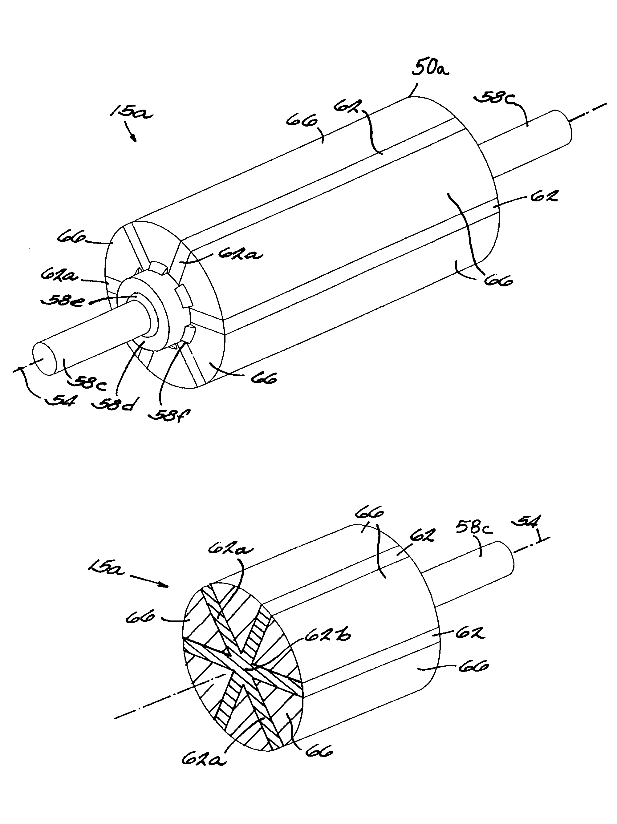
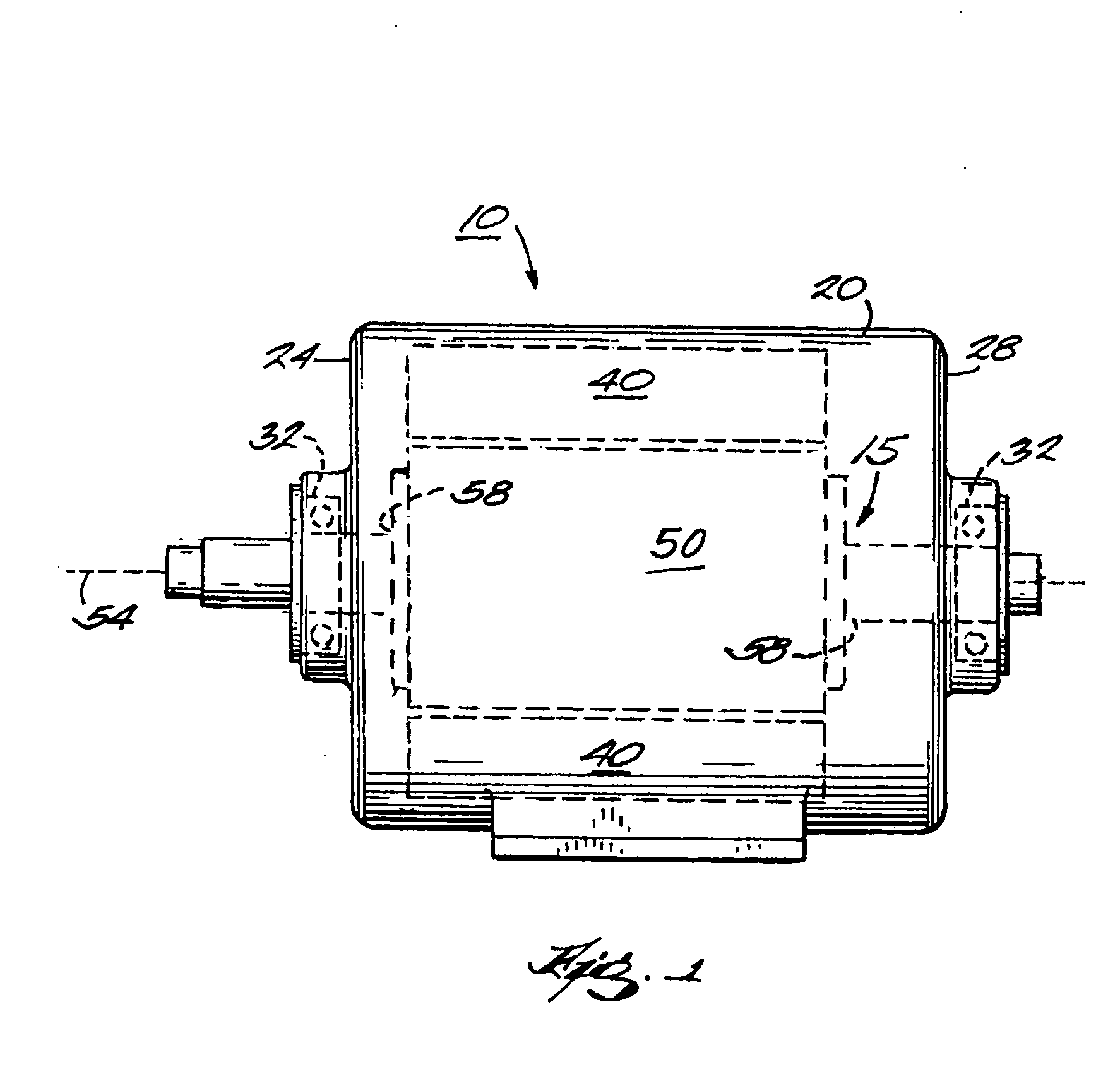
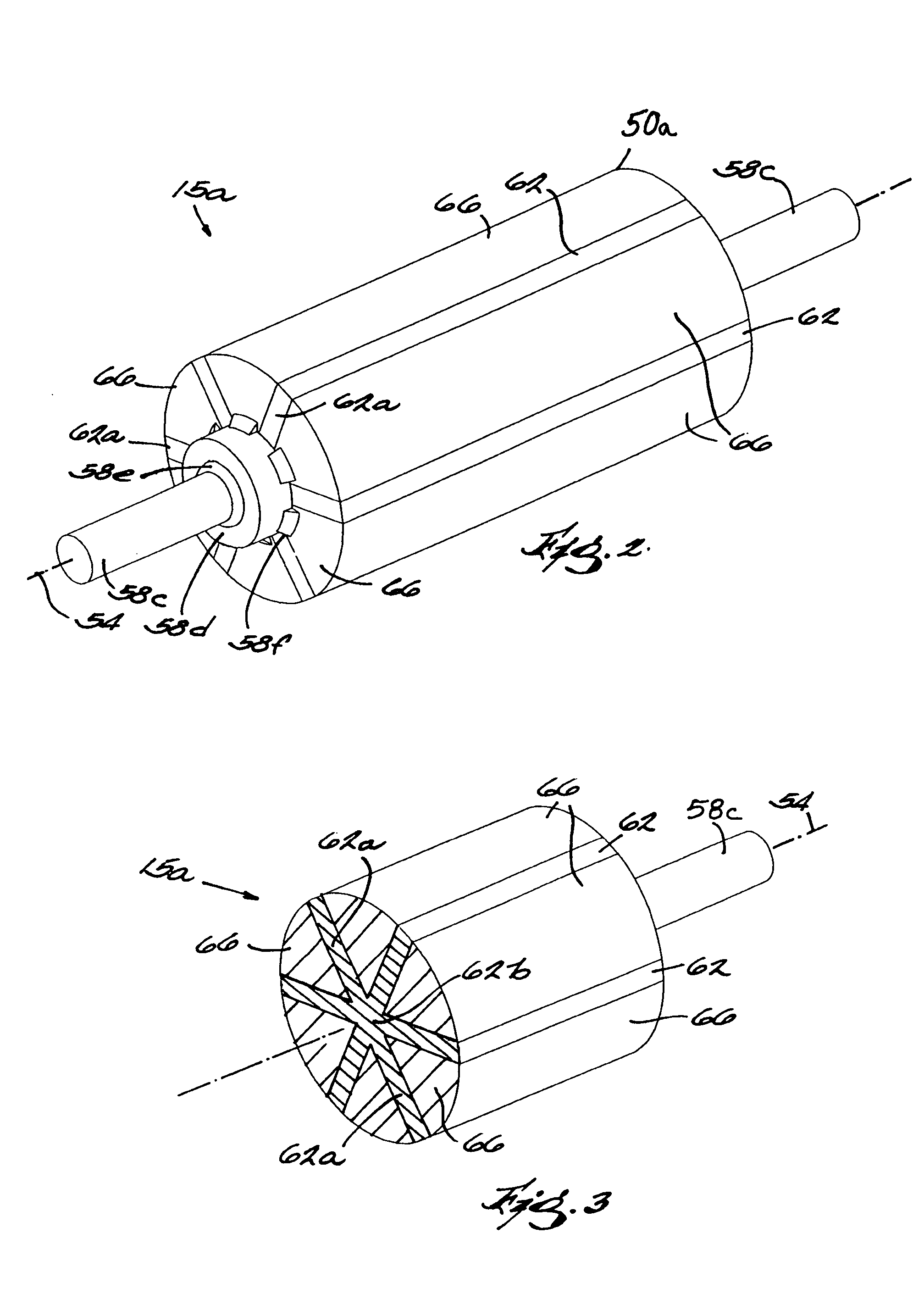
[0022] An electric motor 10 including a spoke permanent magnet rotor assembly 15 embodying the invention is schematically illustrated in FIG. 1. The specific motor embodiment shown is for exemplary purposes. The invention described herein may be used in any type of electric motor having a spoke permanent magnet rotor.

[0023] As illustrated in FIG. 1, the motor 10 includes a motor housing 20 with first and second ends 24 and 28. The motor housing 20 may include a plurality of pieces to accommodate assembly and maintenance. Mounted within each of the first and second ends 24 and 28 of the housing 20 is a respective bearing assembly 32. A stator 40 is mounted within the housing 20. For simplicity, the stator end-windings are not represented in FIG. 1. The spoke permanent magnet rotor assembly 15 is rotationally supported within the housing 20, such that the rotor assembly 50 may turn freely relative to the stator 40.

[0024] The rotor assembly 15 includes a spoke permanent magnet rotor ...


PUM

PropertyMeasurementUnit
ferro-magneticaaaaaaaaaa
perimeteraaaaaaaaaa
axis of rotationaaaaaaaaaa

Abstract

A rotor assembly for an electric motor includes a spoke permanent magnet rotor and a shaft connected thereto. The spoke permanent magnet rotor has an axis of rotation, permanent magnet material, and ferro-magnetic material. The permanent magnet material extends outwardly relative to the axis of rotation to form a plurality of outwardly extending spoke portions of permanent magnet material. The ferro-magnetic material is positioned adjacent to the outwardly extending spoke portions of permanent magnet material. The shaft supports the spoke permanent magnet rotor for rotation about the axis of rotation. The permanent magnet material may circumferentially surround the axis of rotation to form a center portion of permanent magnet material. Further, the axis of rotation may pass through the permanent magnet material. The spoke permanent magnet rotor may be formed using a compaction process and/or an injection molding process.

Description

BACKGROUND OF THE INVENTION [0001] The present invention relates to electric machines, and more particularly to spoke permanent magnet rotors for use in electric motors. [0002] Spoke permanent magnet rotors generally include a plurality of permanent magnets radially arranged around a shaft. The permanent magnets are magnetized tangentially, through the thickness of the permanent magnet, either before or after insertion into the rotor. Magnetic flux generated by the permanent magnets is collected and concentrated by ferro-magnetic pole pieces. Often, the pole pieces are utilized to retain the permanent magnets. [0003] Some examples of spoke permanent magnet rotors are disclosed in U.S. Pat. Nos. 4,631,807; 5,140,211; 5,157,297; 5,200,662; and 5,463,262. [0004] Spoke permanent magnet rotors have a natural flux concentration capability because two circumferentially adjacent permanent magnets contribute to the air-gap flux for each rotor pole. This flux concentration capability allows t...

Claims


Application Information

Patent Timeline
Patent Type & Authority Applications(United States)
IPC IPC(8): H02K1/27H02K15/03
CPCH02K1/2773Y10T29/49012H02K15/03
Inventor IONEL, DAN M.HEIDEMAN, ROBERT J.BARTOS, RONALD P.
Owner REGAL BELOIT AMERICA
Why Eureka
Try Eureka