Control unit for controlling a synchronous motor

a technology of synchronous motor and control unit, which is applied in the direction of electronic commutators, dynamo-electric gear control, and dynamo-electric converter control, etc., can solve problems such as unwanted delays, and achieve the effects of reducing power consumption, eliminating any erroneous differences, and stably controlling the operation of opening and closing doors

Active Publication Date: 2005-04-28
FUJI ELECTRIC CO LTD
View PDF9 Cites 24 Cited by
  • Summary
  • Abstract
  • Description
  • Claims
  • Application Information

AI Technical Summary

Benefits of technology

[0034] According to the first aspect, even when an output signal from the position sensor is identified as abnormal, due to the functional operation of the second controlling means, it is possible to continuously drive the above permanent-magnet-type synchronous motor in correspondence with a predetermined speed instruction value.
[0035] According to the second aspect, while the output signal from the position sensor remains normal, it is possible to reduce power consumption when fully opening the door. On the other hand, when the output signal from the position sensor detects an abnormality, by continuously supplying power to the motor by causing the speed instruction value to be reset to zero when the door is fully opened, even when the door is forced to move due to the intentional application of an unwanted external force, by generating resistant force it is possible to prevent the door from being unduly moved.
[0036] According to the present third aspect, it is possible to eliminate any erroneous difference between the door positional data obtained by integrating the speed instruction value with the actual door position, and thus, even when the signal output from the position sensor becomes abnormal, it is possible to stably control the operations for opening and closing the door.

Problems solved by technology

As the door is not fully closed, unwanted delays will occur.

Method used


Image

  • Control unit for controlling a synchronous motor
  • Control unit for controlling a synchronous motor
  • Control unit for controlling a synchronous motor

Examples


Embodiment Construction

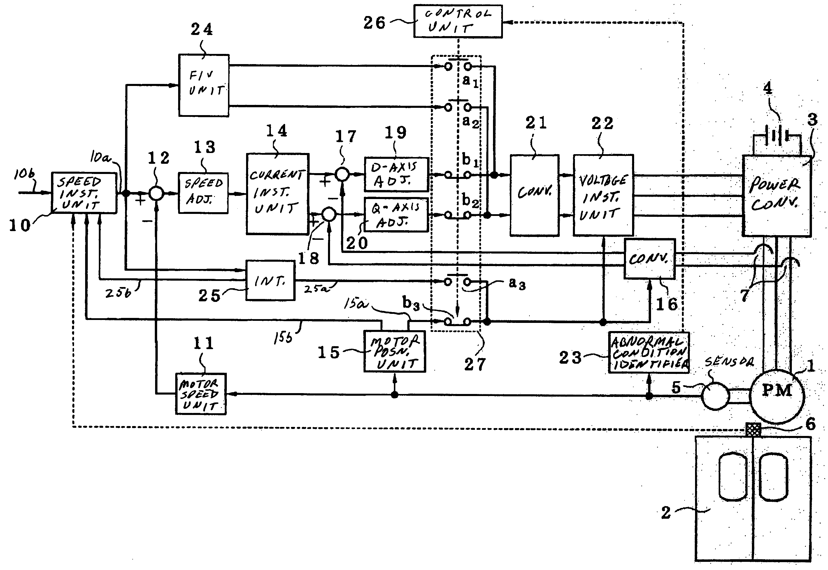
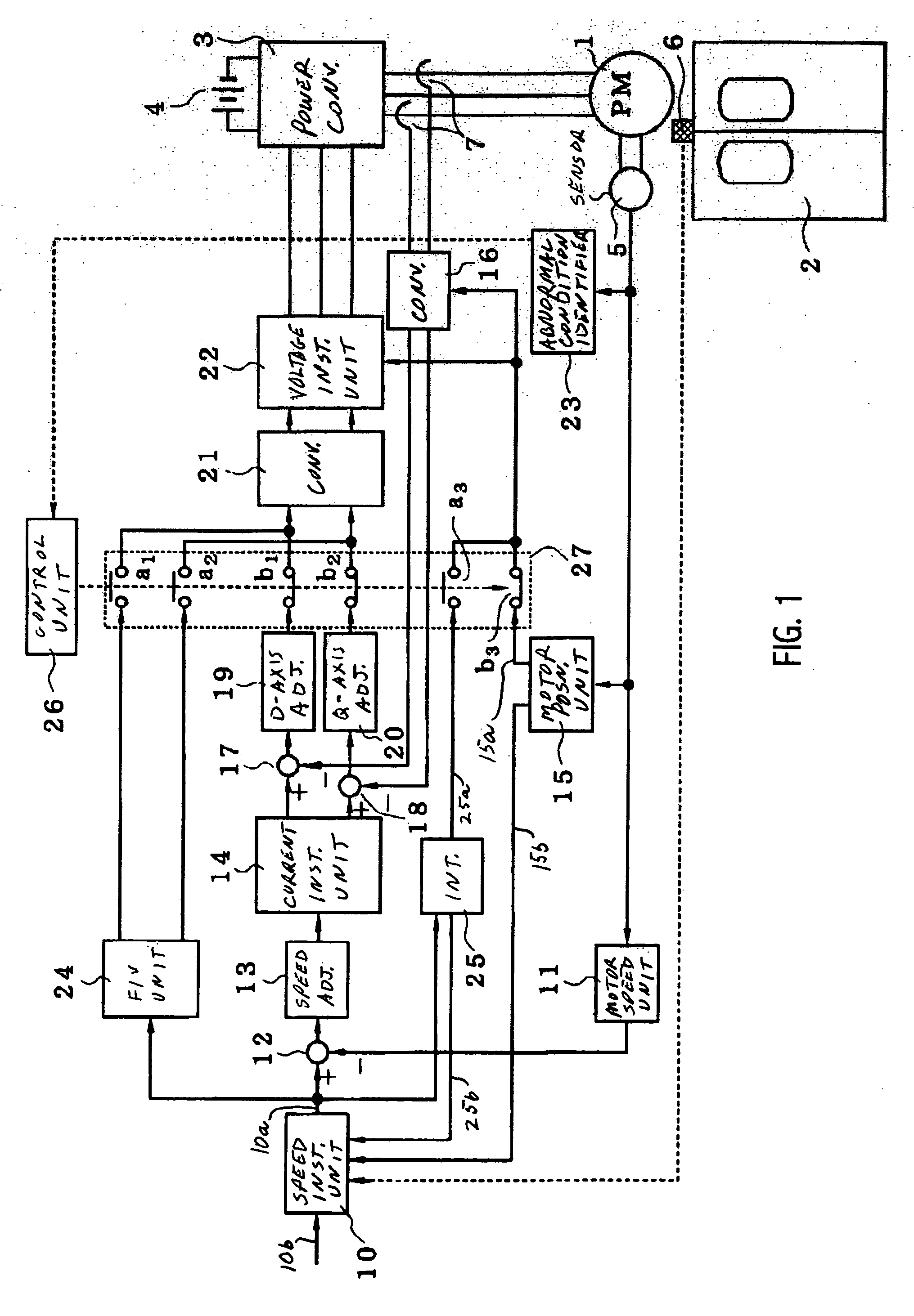
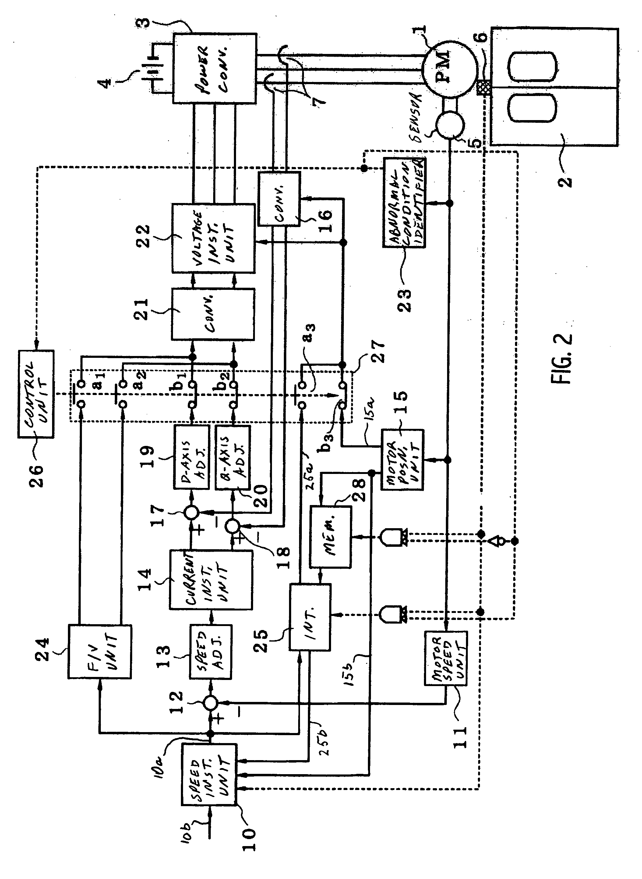
[0040] In the circuit diagram shown in FIG. 1, an F / V arithmetic unit 24, integrating unit 25, switcher control unit 26, and switcher unit 27, have been added to the arrangement shown in FIG. 3. Familiarity with the description of FIG. 3 that was provided above will be assured in the following discussion.

[0041] The F / V arithmetic unit 24 (here, “F” expresses frequency, proportional to the speed-instruction value, and “V” stands for voltage) receives a speed-instruction-value signal 10a from the speed-instruction arithmetic unit 10. The F / V arithmetic unit 24 initially computes the magnitude and phase of a voltage instruction value corresponding to the received speed-instruction-value signal, and then discretely generates a d-axis voltage instruction value and a q-axis voltage instruction value. The voltage instruction values computed by the F / V can respectively be input into the polar-coordinate converter 21 via a pair of normally open contacts a1 and a2 of the switcher unit 27.

[0...


PUM


Abstract

A control unit is provided that controls a motor that opens and closes a door of an electric train such that, if an abnormality is detected by a position sensor, continuation of its open/closing operation can be maintained. The control unit includes an arrangement for computing the actual rotation speed and the magnetic polar position of the motor; a position sensor abnormality-detecting identifier unit for detecting abnormalities in the output of the position sensor; and a first controlling arrangement that generates voltage-instructing values by applying the magnetic polar position so as to cause a speed detection value to correspond to the speed instruction value. The control unit further includes a second controlling arrangement, which in turn includes an F/V arithmetic unit 24 and integrator 25; and a switcher unit 27. The F/V arithmetic unit 24 generates a voltage instruction value having a specific magnitude and phase corresponding to the speed instruction value by utilization of magnetic polar position data that is obtained via integration of a frequency corresponding to the speed instruction value. The switcher unit 27 selects either of the first and second controlling arrangements so as to generate voltage-instructing values for a power converter 3. When the output of the position sensor is normal, the switcher unit 27 selects a specific voltage-instructing value delivered from the first controlling arrangement, whereas if the position of the sensor 5 is abnormal, the switcher unit 27 selects a specific voltage-instructing value delivered from the second controlling arrangement.

Description

CROSS-REFERENCE TO RELATED APPLICATION [0001] This application claims the benefit of priority under 35 USC 119 of Japanese patent application number 2003-366242, filed Oct. 27, 2003, the entire disclosure of which is incorporated herein by reference. BACKGROUND OF THE INVENTION [0002] The present invention relates to a control unit for controlling the operation of a permanent-magnet-type synchronous motor equipped with a position sensor so as to drive the motor with rotation speed that is controlled. More particularly, the present invention relates to a control unit for of a permanent-magnet-type synchronous motor suitable for opening and closing doors of an electric train (such as dual-panel sliding doors of subway cars). [0003]FIG. 3 is a block diagram showing an example of a conventional motor-control unit. The construction and operation of this control unit will be described below. Reference number 1 represents a 3-phase permanent-magnet-type synchronous motors, such as a linear...

Claims


Application Information

Patent Timeline
Patent Type & Authority Applications(United States)
IPC IPC(8): B61D19/02H02P1/46H02P6/06H02P6/08H02P6/16H02P6/17H02P6/28H02P21/00H02P21/22H02P27/06H02P29/00
CPCH02P27/047H02P2207/05H02P29/022H02P21/00H02P29/032
Inventor SATO, YOSHINOBU
Owner FUJI ELECTRIC CO LTD
Why Eureka
Try Eureka