Autonomously assembled space telescope

a space telescope and autonomous assembly technology, applied in the field of space optic systems, can solve the problems of not being fully or easily tested on earth, not yet being accomplished, and not being able to fully or easily support optical or other components, so as to improve optical performance, improve cost efficiency, and improve resolution

Inactive Publication Date: 2005-04-28
THE BOEING CO
View PDF5 Cites 19 Cited by
  • Summary
  • Abstract
  • Description
  • Claims
  • Application Information

AI Technical Summary

Benefits of technology

[0008] The present invention will also enable significantly higher resolution astronomy through the use of larger apertures having a filled aperture design. The filled aperture design of the AAST gives better optical performance as compared with sparse aperture optics and multi-telescope systems due to the lack of side lobes and also due to the least post-processing of image data.
[0009] Further, the present invention may be potentially more cost effective because the components of the AAST can be robotically assembled in space to a high precision, and robotic assembly reduces the risk of requiring astronauts for assembly of large space optics.

Problems solved by technology

In the past, considerable effort has been spent attempting to design reflective telescopes having larger and larger optics, but two basic difficulties have arisen: achieving and maintaining sub-wavelength tolerances over the large apertures, and designing telescopes which are light and compactly packaged for launch and eventual deployment into orbit.
This has not yet been accomplished.
In some lightweight designs, optical or other components are not self-supporting in an earth gravity environment and thus cannot be fully or easily tested on earth prior to launch.
The payload mass capacity and fairing size of the launch vehicle limits the optics size.
Still, the size and mass constraints of the launch vehicle limit the primary diameter to 6.5 meters with the current state of technologies in segment, telescope structure and deployment.

Method used


Image

  • Autonomously assembled space telescope
  • Autonomously assembled space telescope
  • Autonomously assembled space telescope

Examples


Embodiment Construction

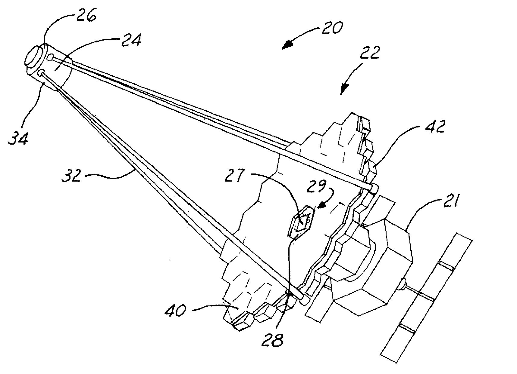
[0023] Referring now to FIG. 1, a reflecting telescope having a filled aperture design is shown generally as 20, herein shown contained on an orbiting satellite 21. Infrared and visible radiation from an astronomical object (e.g., a star) is collected, reflected and focused by a primary mirror 22 (preferably concave) towards a smaller secondary mirror 24 (preferably convex). Just before it gets to the focus the smaller secondary mirror 24 at the top 26 of the telescope 20 reflects this steeply converging beam of radiation and directs it downwards, now converging much more slowly, through a central hole 28 in the primary mirror 22 to an optical beam path 29 including an optional tertiary mirror 27, below, which directs it to an instrument focal station (not shown) contained within the satellite 21, wherein an onboard computer converts the data into a form that can be beamed to earth via communications satellites. The secondary mirror 24 has a support side surface 34 to which is coupl...


PUM


Abstract

A method for autonomously assembling a segmented filled aperture telescope (“AAST”) in space using modular components that are launched into orbit using multiple launches. In one embodiment, a plurality of interlocking modular mirror backing structure segments, with or without an edge truss, are introduced to a satellite. To this are coupled a plurality of modular segmented optics to form a primary concave mirror. In another embodiment, the mirror backing structure and modular optics segments are formed as a single modular unit, with a plurality of these units coupled together to form the primary concave mirror. The modular concept allows primary mirrors of virtually limitless size to be formed in space with or without using astronauts.

Description

BACKGROUND OF INVENTION [0001] The present invention generally relates to space optic systems and more specifically to an autonomously assembled space telescope. [0002] The progress in large aperture telescopes has been quite remarkable over the last two decades. In space, the Hubble Space Telescope with a 2.4-meter monolithic primary mirror has been operating since 1993. Work on the James Webb Space Telescope (JWST) with a 6.5-meter deployable, segmented primary mirror has recently begun, and is scheduled for launch in 2011. In the ground-based optics arena, the 10-meter diameter Keck I and Keck II telescopes and 9.2-meter diameter Hobby Eberly telescopes became operational between 1992 and 1996. [0003] In the past, considerable effort has been spent attempting to design reflective telescopes having larger and larger optics, but two basic difficulties have arisen: achieving and maintaining sub-wavelength tolerances over the large apertures, and designing telescopes which are light ...

Claims


Application Information

Patent Timeline
Patent Type & Authority Applications(United States)
IPC IPC(8): G02B7/182G02B7/183G02B17/06
CPCG02B17/061G02B7/183
Inventor BASU, SANTANU
Owner THE BOEING CO
Why Eureka
Try Eureka