Seal ring and rolling bearing unit with seal ring

a technology of sealing ring and rolling bearing, which is applied in the direction of hubs, mechanical equipment, transportation and packaging, etc., can solve the problems of degrading the sealing performance and durability of the seal lips, the difficulty of sufficiently preventing foreign objects from entering the above internal space, and the deformation of the sealing performance. , to achieve the effect of reducing the frictional resistance of the sliding contact region, reducing the force to constrain, and easy generation

Inactive Publication Date: 2005-04-28
NSK LTD
View PDF6 Cites 30 Cited by
  • Summary
  • Abstract
  • Description
  • Claims
  • Application Information

AI Technical Summary

Benefits of technology

[0033] In contrast to this, in the case of the seal ring according to the present invention, the most thin portion provided at the base end portion functions as a hinge to decrease the force to constrain on the most thick portion located in the leading edge side of this most thin portion in the radial direction and in the axial direction. Because of this, the above hoop force . is easily generated. As a result, even if the central axis of the seal ring is tilted relative to the central axis of the member providing the counterpart surface with which the tip edge portion of the seal lip constituting this seal ring comes in slidable contact to make uneven the distance between the metal core constituting the above seal ring and the counterpart surface, the contact surface pressure between the tip edge portion of the above seal lip and the counterpart surface can be kept uniform. As a result of the uniform contact surface pressure at the slidably contacting region, it is possible to let this tip edge portion effectively follow the displacement of the counterpart surface without a particularly high surface pressure at the slidably contacting region between the tip edge portion of the seal lip and the counterpart surface. Then, as described above, it is possible to decrease the frictional resistance of the slidably contacting region between the seal lip and the counterpart surface and improve the durability of this seal lip, without compromising the sealing performance of this seal lip.

Problems solved by technology

As a result, the sealing performance of the above seal lip 22 is degraded and therefore it is difficult to sufficiently prevent foreign objects from entering the above internal space 13.
In such a case, the sliding contact condition between the tip edge portions of the seal lips 22 and 27 and the corresponding counterpart surfaces becomes uneven, and therefore there is a problem that the sealing performance and the durability of the seal lips 22 and 27 are degraded and the like problem.
However, when the interference is set to be somewhat larger, it results, as the cost of securing the sealing performance during a turning motion, in that the sliding resistances of the above respective seal lips 22 and 27 increases and, in addition to this, that these respective seal lips 22 and 27 tend to wear and become limp.
However, it is also not preferred that they tend to wear and become limp because the degradation of the durability of the rolling bearing results therefrom.
As a result, the contact pressure at the slidably contacting region between the tip edge portion of this seal lip and the above slinger is decreased with time, and there is the possibility that the initial sealing performance cannot be maintained at a relatively earlier stage.

Method used


Image

  • Seal ring and rolling bearing unit with seal ring
  • Seal ring and rolling bearing unit with seal ring
  • Seal ring and rolling bearing unit with seal ring

Examples


Embodiment Construction

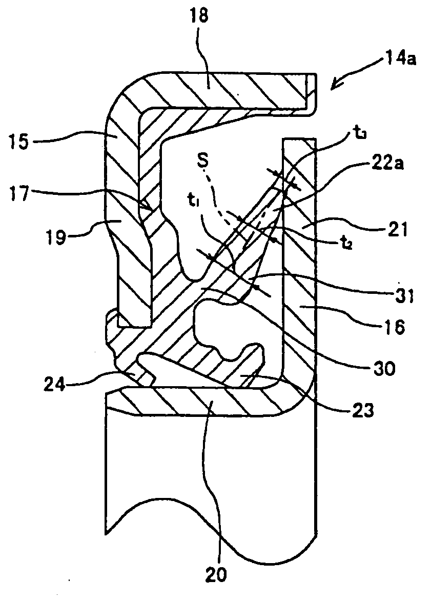
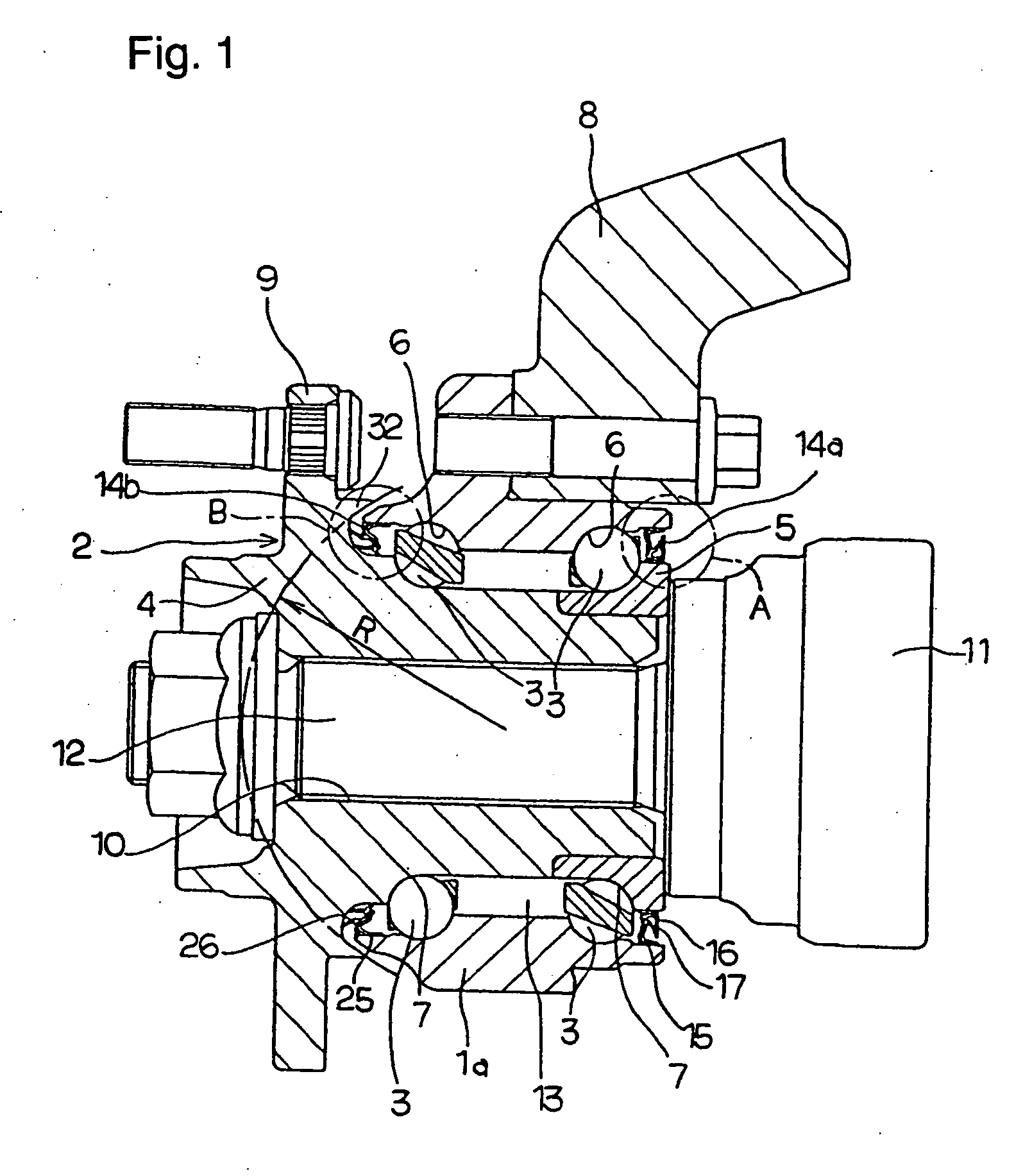
[0056]FIGS. 1 and 2 show a first example of the embodiment of the present invention. Incidentally, the characteristics of this example resides in that the sealing performance and the durability of a seal lip 22a are improved by devising the profile of the seal lip 22a constituting a seal ring 14a which serves to close the opening at the inner end of the internal space 13 with a plurality of rolling members 3, 3 provided therein. The structures and the functionality of the other elements are similar to those of the prior art structure as described above, and therefore, while redundant explanation is not repeated or is simplified with like symbols applied to like members, the following description is focused on the characteristic structure of the present invention differing from the above prior art structure.

[0057] The above seal lip 22a, which is called a side lip, is provided with a most thin portion 30 at the base end portion thereof by setting down the opposite surfaces of this b...


PUM


Abstract

It is intended that the rotation resistance is decreased while the durability and seal performance are kept in the rolling bearing unit with seal ring.
The most thin wall-thickness portion 30 is provided in the vicinity of the base end of the seal lip 22a projecting laterally in sliding contact with the mating surface. The most thick wall thickness portion 31 is provided adjacent to the most thin wall thickness portion 30 on the tip end side. The thickness is gradually decreased from the most thick wall thickness portion 31 to the tip end. Further, the ratios of thickness in the respective portions 22a are properly controlled.

Description

CROSS-REFERENCE TO RELATED APPLICATION [0001] The present application is a continuation of International Application No. PCT / JP03 / 03527 which was filed on Mar. 24, 2003, which is herein incorporated by reference.TECHNICAL FIELD [0002] This invention is related, for example, to the improvement of a seal ring for closing the opening end of the rolling bearing unit for supporting the wheels of a vehicle (automobile) on a suspension device. More specifically, it is intended to improve the sealing performance, i.e., the performance of preventing foreign objects such as muddy water from entering the inside of the internal space in which rolling members are arranged and preventing a grease applied inside of this internal space from leaking out, and at the same time to realize a low friction structure and a low abrasion structure. Then, it is an object to improve the traveling performance of a vehicle represented by fuel consumption performance and acceleration performance and simplify the ...

Claims


Application Information

Patent Timeline
Patent Type & Authority Applications(United States)
IPC IPC(8): B60B27/00B60B37/00F16C33/78F16J15/32
CPCB60B27/00B60B37/00F16C33/7823F16C2326/02F16J15/3264F16C33/7879F16C19/184F16C19/386
Inventor TAKEHARA, TETSUYUKAWA, KINJI
Owner NSK LTD
Why Eureka
Try Eureka