Vehicle suspension control system and suspension control method

a technology of suspension control system and vehicle suspension, which is applied in the direction of bicycle equipment, navigation instruments, instruments, etc., can solve the problems of vehicle steering instability and/or riding discomfort, and achieve the effect of maintaining steering stability and riding comfort, favorably and maintaining steering stability of the vehicl

Inactive Publication Date: 2005-04-28
AISIN AW CO LTD
View PDF7 Cites 56 Cited by
  • Summary
  • Abstract
  • Description
  • Claims
  • Application Information

AI Technical Summary

Benefits of technology

[0017] Accordingly, when the vehicle approaches the corner, if the road surface has a degree of roughness corresponding to a good road surface, the damping force of the suspension means before entering the turn at the corner is controlled in a manner corresponding to a good-road adjustment, thus favorably maintaining steering stability of the vehicle in turning the corner. On the other hand, if the degree of roughness of the road surface where the vehicle approaches the corner does not corresponding to a good road surface, the damping force of the suspension means is controlled in a manner corresponding to the bad-road adjustment when entering the corner, thus, in this case also, favorably maintaining steering stability and riding comfort of the vehicle in turning the corner.
[0018] In cornering if, upon entering the turn around the corner, after detection of a good road surface in the approach to a corner and output of a good road adjustment, the detected degree of roughness no longer corresponds to a good road surface, a bad-road adjustment to the damping force of the suspension means is calculated as above and output to the suspension means. Accordingly, when the vehicle approaches a corner, in the case where the road surface changes from a degree of roughness corresponding to a good road surface to a degree of roughness not corresponding to a good road surface, the damping force of the suspension means is thereafter controlled in accordance with the bad-road adjustment amount so that, in travel around the corner, steering stability and riding comfort are maintained.

Problems solved by technology

However, in the above suspension control system, the corner information does not include information about the state of the road surface at the corner.
Accordingly, where the road surface at the corner is rough or slippery, for example, even if suspension control is previously effected as in the above, immediately before entering the corner, without taking into account the state of the road surface at the corner, the vehicle, after entering the corner turn, will have instability in steering and / or riding discomfort.

Method used


Image

  • Vehicle suspension control system and suspension control method
  • Vehicle suspension control system and suspension control method
  • Vehicle suspension control system and suspension control method

Examples


first embodiment

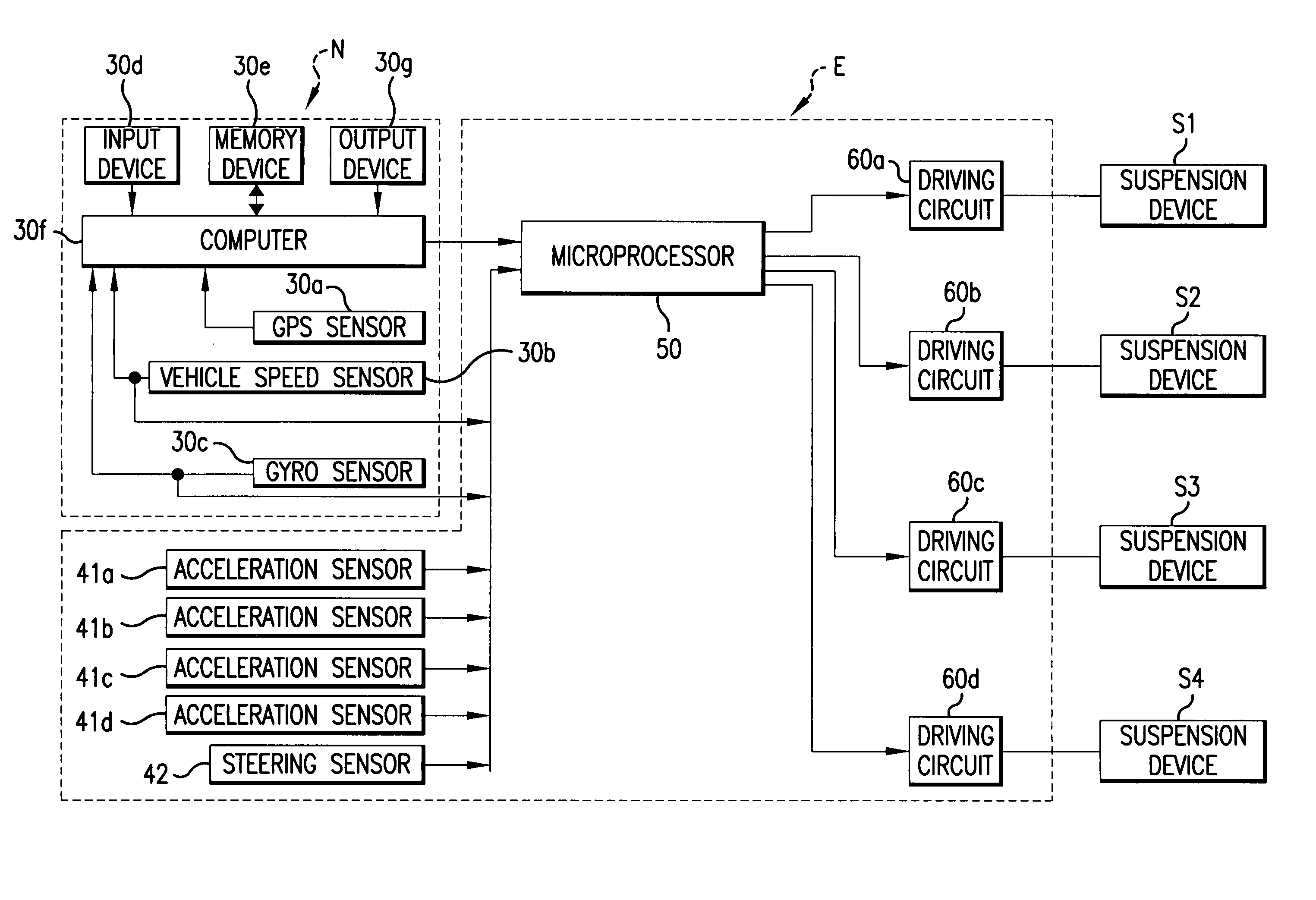
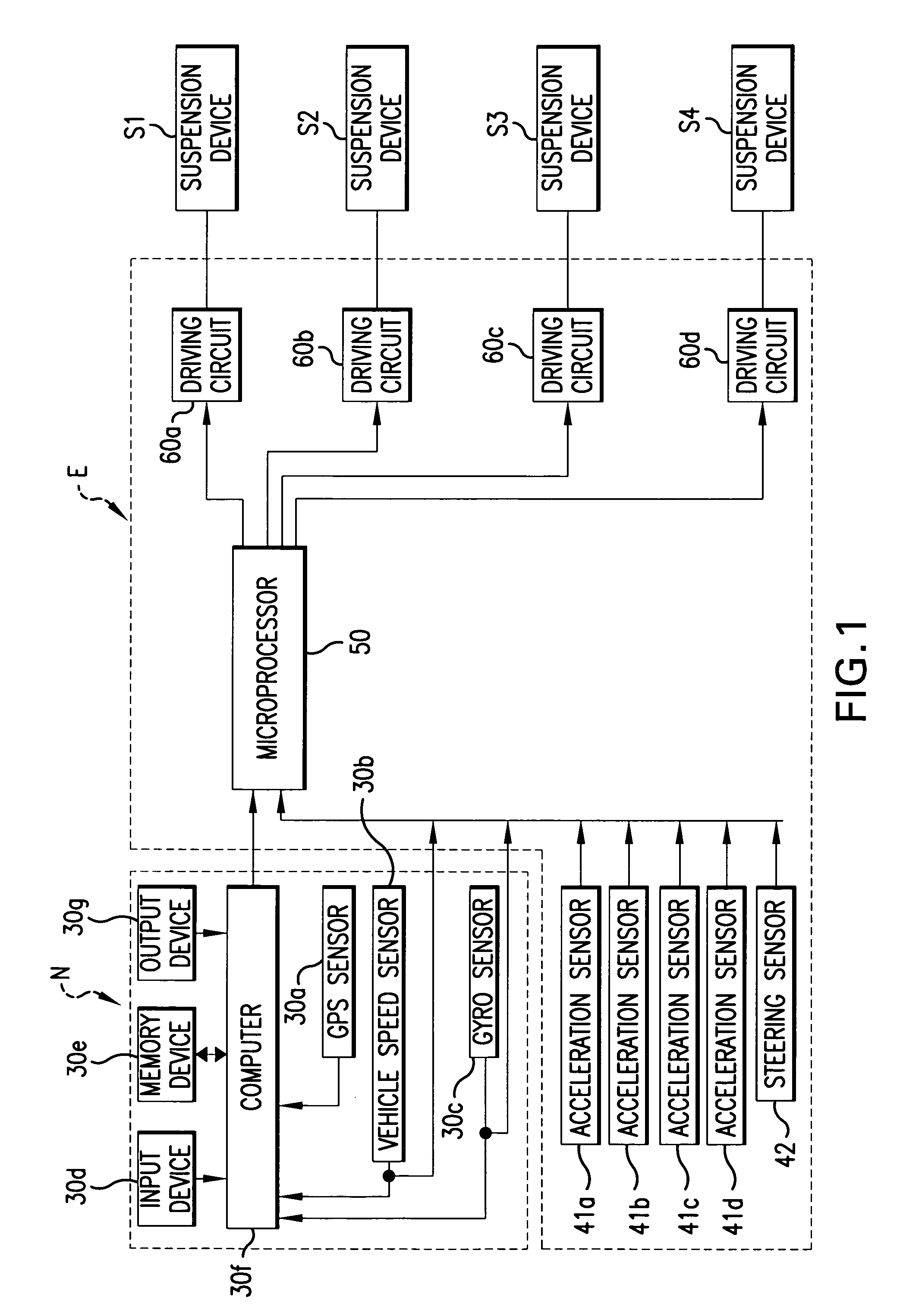
[0117]FIG. 1 shows one example of a suspension control system wherein suspension units S1-S4 are controlled by an electronic control unit E.

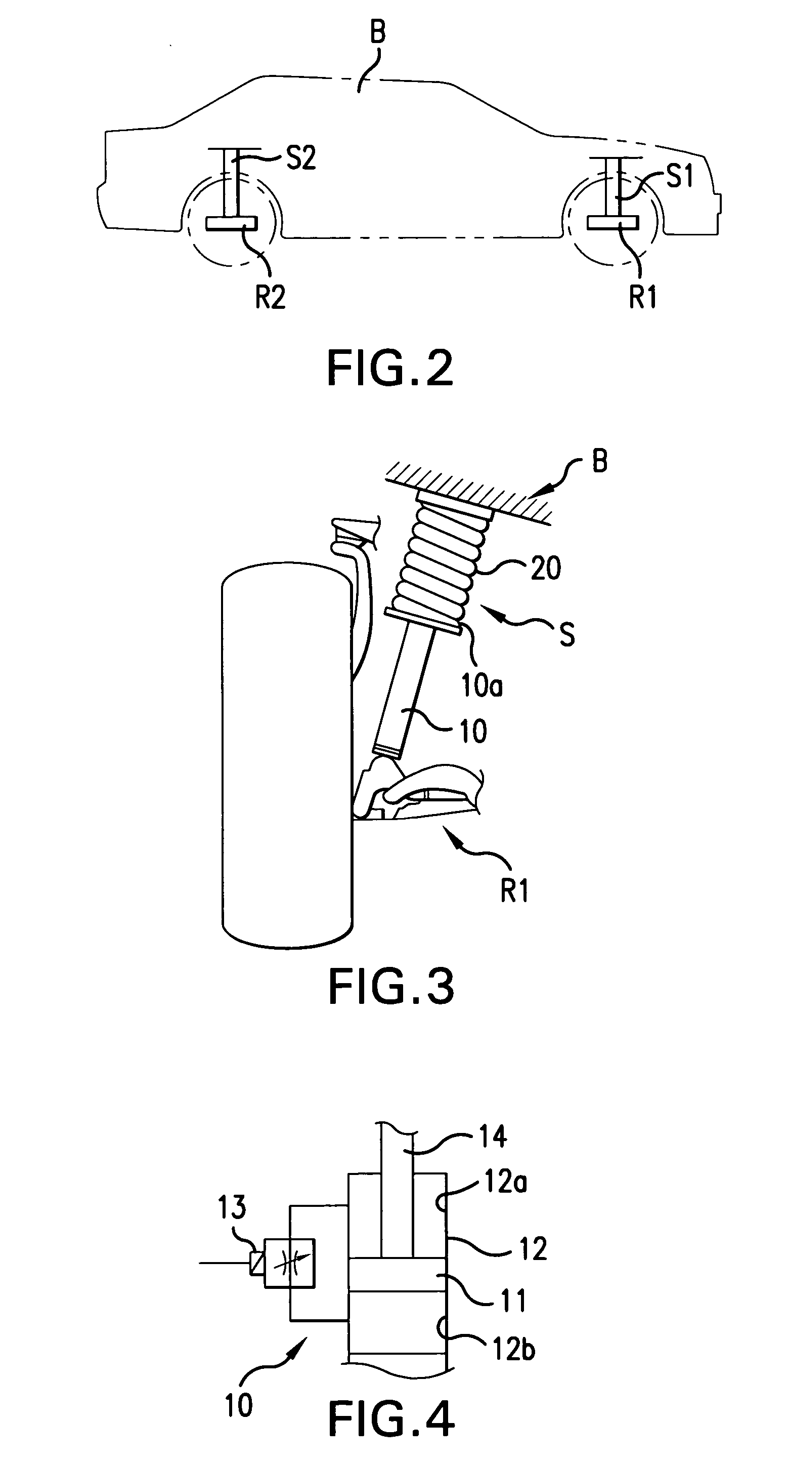
[0118] The suspension unit S1 is interposed between a wheel support element R1, provided at a point close to the right-sided front wheel of the automobile and a corresponding portion of the frame B of the vehicle, as shown in FIG. 2. The wheel support element, to which the lower end of the shock absorber attaches, may be different for front and rear wheels and for different vehicles, e.g. axle housing, lower suspension arm, steering knuckle, bearing housing or motor housing.

[0119] The suspension unit S1 has a damper 10 and a coiled spring 20, as shown in FIG. 3. The damper 10 at its lower end is supported on the wheel support element R1. The coiled spring 20 is coaxially fitted over the exterior of the damper 10, extending from a flange 10a provided at an axially intermediate point on the exterior surface of the damper 10 to the frame B. The c...

second embodiment

[0196]FIG. 17 shows a second embodiment of the invention. This second embodiment employs rotational speed sensors 43a, 43b as shown in FIG. 17 in place of the acceleration sensors 41a-41d of the first embodiment. These rotational speed sensors 43a, 43b are respectively provided in positions close to the driving wheels of the automobile to detect rotational speeds of the respective drive wheels.

[0197] The second embodiment utilizes the control program represented by the flowchart of FIG. 18, instead of the program of the flowchart of FIG. 8 in the first embodiment. Further, the second embodiment utilizes the slip-degree setting routine 130a of FIG. 19 and the damping-level determination routine 140a of FIGS. 20 and 21, instead of the roughness-degree setting routine 130 of FIG. 9 and damping-level determination routine 140 of FIGS. 10 and 11, utilized in the first embodiment.

[0198] In the second embodiment, when the navigation basic routine 100 of FIG. 5 to step 120 has been execut...


PUM


Abstract

When a vehicle approaches a corner, a microprocessor, responsive to a determination that a detected degree of roughness of the road surface corresponds to the most moderate roughness, sets the damping force for the vehicle suspension units, on the basis of the detected degree of roughness, vehicle speed and a radius of curvature and corner information from a navigation system. In the case of a determination that the detected degree of roughness does not correspond to the most moderate roughness, a damping level is set on the basis of the detected degree of roughness, vehicle speed and radius of curvature.

Description

CROSS-REFERENCE TO RELATED APPLICATIONS [0001] This application claims, under 35 USC 119, priority of Japanese Application No. 2003-336127 filed Sep. 26, 2003 and Japanese Application No. 2003-346000 filed Oct. 3, 2003, the teachings of which are incorporated by reference herein, in their entirety, including the specifications, drawings and abstracts. Copending application of Fumiharu OGAWA, Ser. No. ______ (Attorney Docket No. AW-C463), entitled “SUSPENSION CONTROL SYSTEM AND SUSPENSION CONTROL METHOD FOR VEHICLE” and filed on even date herewith discloses and claims related subject matter. BACKGROUND OF THE INVENTION [0002] 1. Field of the Invention [0003] The present invention relates to a vehicle suspension control system and to a suspension control method. [0004] 2. Description of the Related Art [0005] According to the suspension control system disclosed in JP-A-9-114367, suspension control is initiated immediately before the automobile enters a turn around a corner in the cour...

Claims


Application Information

Patent Timeline
Patent Type & Authority Applications(United States)
IPC IPC(8): G09B29/00B60G17/015B60G17/0165B60G17/08G01C21/00G08G1/0969
CPCB60G2401/16B60G2500/10B60G2600/184B60G2800/162B60G2800/916B60G2400/824B60G17/08B60G2400/102B60G2400/41B60G2400/821B60G17/0165
Inventor OGAWA, FUMIHARU
Owner AISIN AW CO LTD
Why Eureka
Try Eureka